Paint sprayer and pressure washer assembly

a sprayer and pressure washer technology, applied in the direction of lighting and heating apparatus, cleaning using liquids, combustion types, etc., can solve the problem of limited system

Inactive Publication Date: 2006-05-18
BLOCK & DECKER
View PDF11 Cites 55 Cited by
  • Summary
  • Abstract
  • Description
  • Claims
  • Application Information

AI Technical Summary

Problems solved by technology

Although currently available pressure washer systems have greatly increased the ease and eff...

Method used


Image

  • Paint sprayer and pressure washer assembly
  • Paint sprayer and pressure washer assembly
  • Paint sprayer and pressure washer assembly

Examples


Embodiment Construction

[0014] Reference will now be made in detail to the presently preferred embodiments of the invention, examples of which are illustrated in the accompanying drawings.

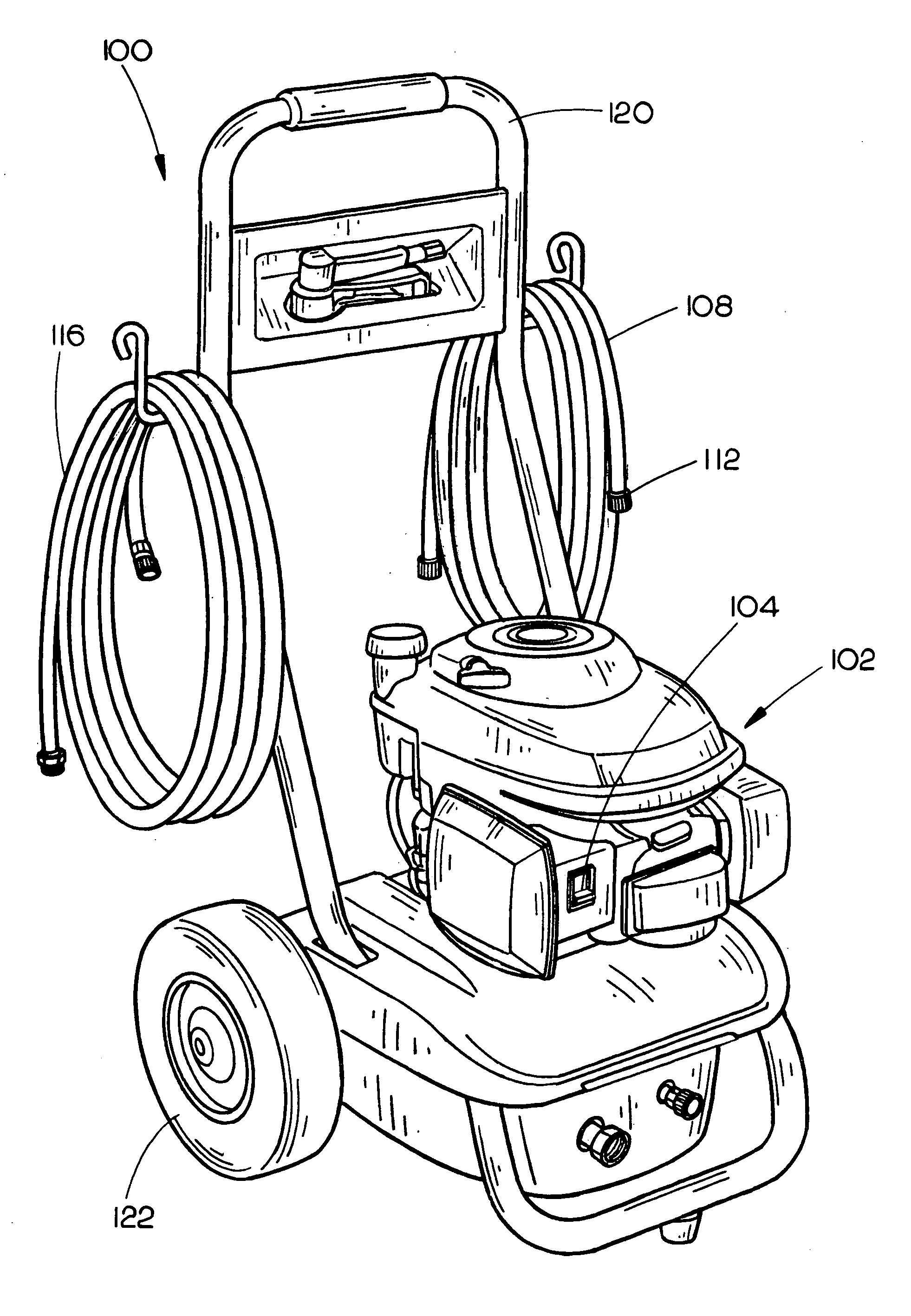
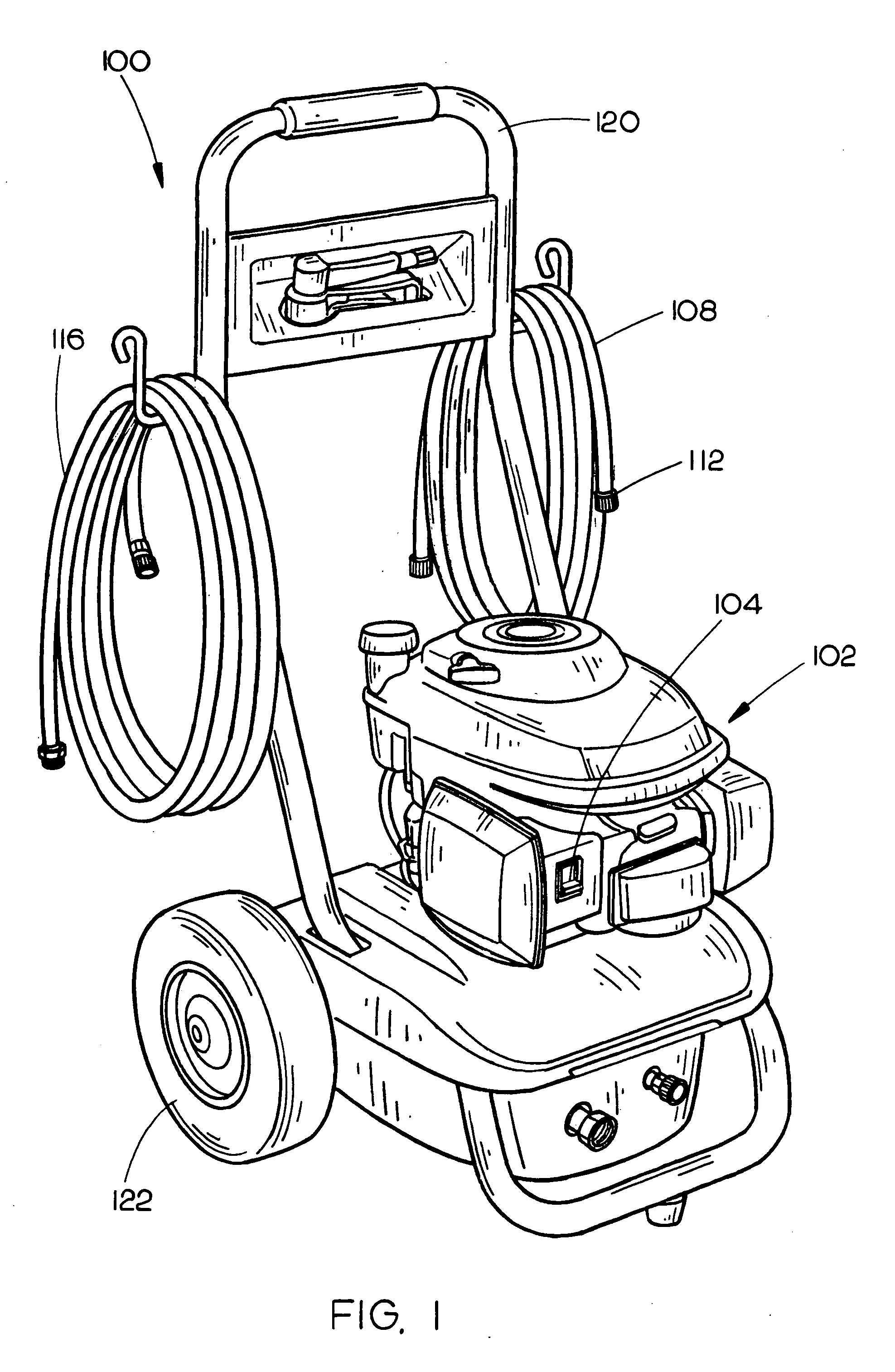
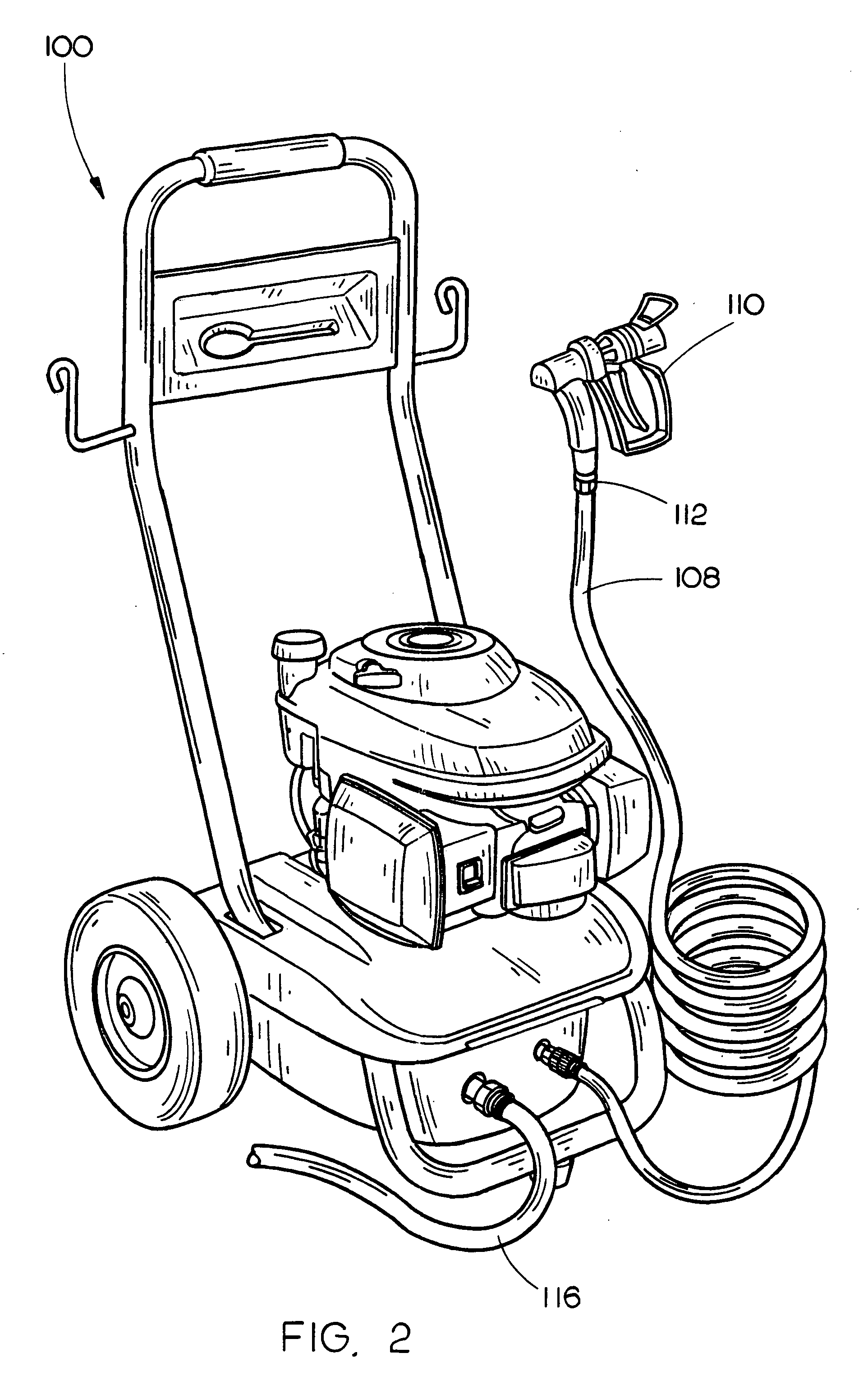
[0015] Referring to FIGS. 1-4, a paint sprayer and pressure washer assembly in accordance with the present invention is disclosed wherein such assembly may function as a pressure washer and a paint sprayer. The paint sprayer and pressure washer assembly 100 includes a motor assembly 102 having a motor capable of operating at different speeds. For instance, the motor may turn a drive shaft at a first speed to generate a first rotational velocity until an alternate speed is selected using a switch 104 or the like, at which point the motor may turn the drive shaft at a second speed to generate a second rotational velocity. In turn, rotational velocity is reciprocated into pressure and / or flow rate whereby a first rotational velocity generates a first pressure and / or flow rate and the second rotational velocity generates a s...


PUM


Abstract

A paint sprayer and pressure washer assembly is comprised of a universal motor capable of operating at at least a first speed and a second speed. Further, a pump assembly is coupled to the motor for pressuring a fluid for delivery of the fluid to a surface. In use, the motor drives the pump at one of the first speed for pumping a first fluid so that the first fluid is output at a first pressure and flow rate and the second speed for pumping a second fluid so that the second fluid is output at a second pressure and flow rate.

Description

CROSS-REFERENCE TO RELATED APPLICATIONS [0001] The present application claims the benefit under 35 U.S.C. 119(e) of U.S. Provisional Application Ser. No. 60 / 533,821, filed Dec. 31, 2003 which is herein incorporated by reference in its entirety.FIELD OF THE INVENTION [0002] The present invention relates generally to the field of pressurized fluid delivery systems, and more particularly to a paint sprayer and pressure washer assembly for selectively supplying one of pressurized paint or water to a surface. BACKGROUND OF THE INVENTION [0003] Pressurized fluid delivery systems, such as pressure washers, are often employed to perform various household tasks. For example, the exterior of a house may be cleaned much more efficiently as well as more thoroughly with a pressure washer than compared to the traditional method of using a hose, bucket and scrub brush. In addition, such systems are commonly employed to perform other household tasks such as preparing a surface for painting or the c...

Claims


Application Information

Patent Timeline
IPC IPC(8): A01G25/09B05B9/06F23D14/28B05B7/30
CPCB05B9/0855B08B3/026
Inventor DEXTER, SHANE
Owner BLOCK & DECKER
Why Eureka
Try Eureka