
Step-on receptacle with tip prevention

a technology of receptacles and receptacles, applied in the field of receptacles, can solve the problems of receptacles prone to tip rotation and receptacles to tip, and achieve the effect of resisting the receptacles' tendency to rota

Active Publication Date: 2006-05-18
AMERICAN PLASTICS LLC
View PDF99 Cites 56 Cited by
  • Summary
  • Abstract
  • Description
  • Claims
  • Application Information

AI Technical Summary

Benefits of technology

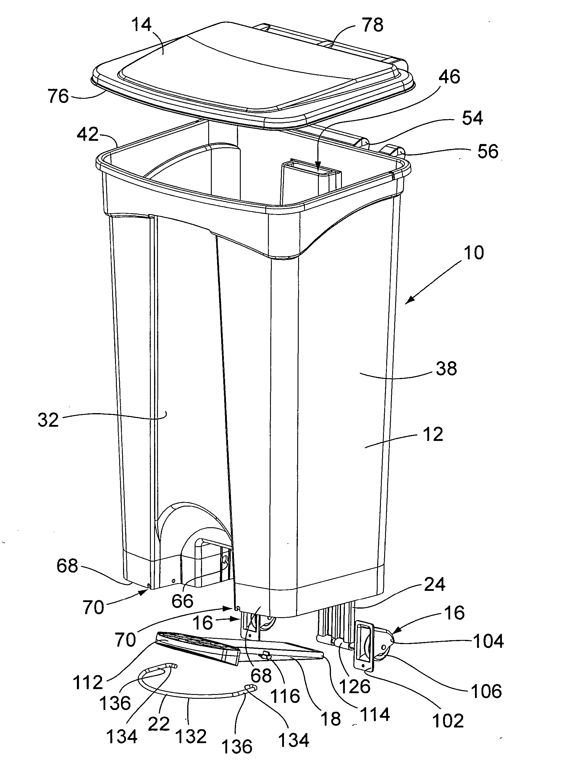
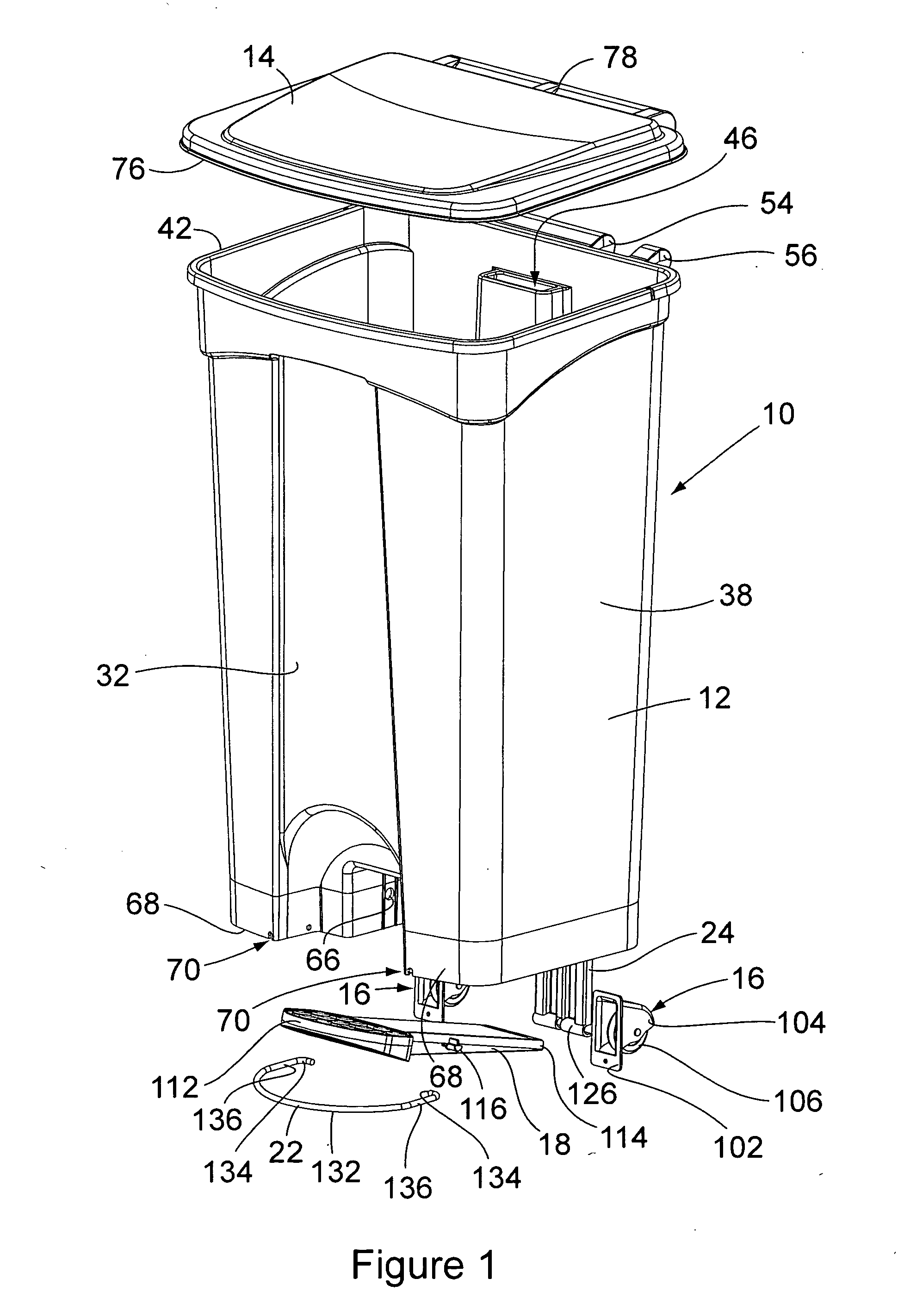
[0007] In a first preferred embodiment, the present invention provides a refuse receptacle with a lid and a foot pedal placed near a bottom member of the receptacle. The foot pedal opens the lid when a user steps on the pedal. The refuse receptacle of the current embodiment also includes a wire hoop protruding from the front of the receptacle and surrounding the foot pedal. With the receptacle positioned upright on a surface, the hoop is positioned beneath the foot pedal and slightly above the surface. If a user exerts too much force when stepping on the pedal, the hoop engages against the surface and prevents the receptacle from tipping over. Optionally, the hoop may attach to the receptacle without fasteners by, for example, being expanded at an open end of the hoop and slipped over an attachment structure on the receptacle, thus simplifying the receptacle's construction.
[0009] In a third preferred embodiment, the present invention provides a method of containing articles. The method includes applying a force to a lever that is operably connected to a receptacle for containing articles. The force on the lever moves a top cover of the receptacle from a closed position to an opened position and tends to cause the receptacle to tip over. The receptacle also has a bottom member and a plurality of sidewalls extending from the bottom member. In the closed position the top cover is substantially adjacent the upper ends of the sidewalls. In the opened position an edge of the top cover is spaced apart from an upper end of at least one of the sidewalls. Additionally, the method includes resisting the tendency of the receptacle to tip over with a support that extends from the receptacle and that abuts the receptacle along at least a portion of the support.

Problems solved by technology

Applying force to the lever, though, causes the receptacle to tend to rotate (i.e. tip over).
The force on the lever moves a top cover of the receptacle from a closed position to an opened position and tends to cause the receptacle to tip over.

Method used


Image

  • Step-on receptacle with tip prevention
  • Step-on receptacle with tip prevention
  • Step-on receptacle with tip prevention

Examples


Embodiment Construction

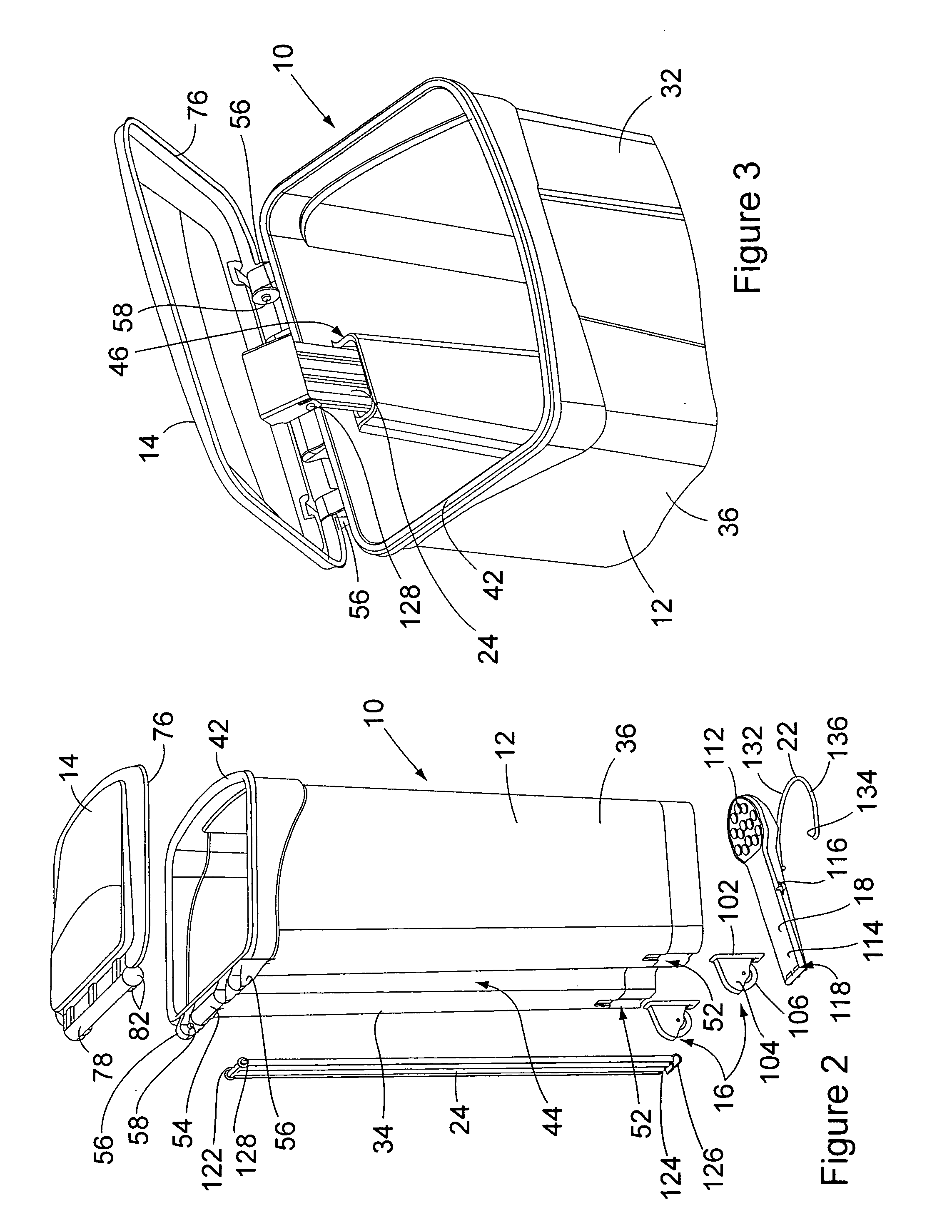
[0018] The receptacle 10 of the invention has a novel, simplified construction that enables the receptacle 10 to be constructed of only seven basic component parts. Preferably all of these parts, except one, is constructed of a plastic material. It is preferred that each of the parts be formed monolithically. Furthermore, the simplified construction of the receptacle 10 enables the component parts of the receptacle to be assembled together without the use of separate threaded fasteners, such as screws or nuts and bolts, if so desired. The seven component parts include a hollow receptacle housing 12, a lid 14 that is attached to the housing, a pair of wheel assemblies 16 that are attached to the housing, an actuator foot pedal 18 that is attached to the housing, a stabilizing hoop 22 that is attached to the housing, and an actuator link 24 that is attached between the foot pedal 18 and the lid 14.

[0019] The receptacle housing 12 has a construction that is similar to that of prior ar...


PUM


Abstract

A novel construction of a stabilized receptacle is provided in which the receptacle is comprised of only seven separate component parts that are assembled together without the use of separate threaded fasteners. In addition, the receptacle is provided with a stabilizing hoop that extends forwardly from the receptacle around the foot pedal of the receptacle and stabilizes the receptacle, preventing movement of the receptacle when the foot pedal is depressed.

Description

FIELD OF THE INVENTION [0001] This invention relates generally to receptacles for containing articles and, more particularly, to receptacles that include foot pedals for opening a lid of the receptacle. BACKGROUND OF THE INVENTION [0002]“Step-on receptacles” are used to contain articles that the user typically considers to be debris or refuse. These receptacles include a hollow body, a lid covering the top of the hollow body, and a foot pedal operably connected to the lid so that when a user steps on the pedal the lid opens. In locations in which biologically hazardous materials (i.e. biohazards) may be encountered, step-on receptacles allow a user to hold an article while operating the lid with a foot so that the user can deposit the article in the receptacle without using either hand. Because the user can operate the receptacle in a “hands-free” manner, the user can deposit articles in the receptacle without potentially spreading foreign matter between the receptacle, the article,...

Claims


Application Information

Patent Timeline
IPC IPC(8): B62B1/00
CPCB65F1/1473B65F1/163B65F1/1646
Inventor NIEMEYER, DUANEHAGGIN, MICKEYWAREHEIM, ROBERTDICKINSON, TOM
Owner AMERICAN PLASTICS LLC
Learn More