Illuminating unit with reflective collimator and image projection system including the same

a technology of reflective collimators and illumination units, applied in semiconductor devices, lighting and heating apparatus, instruments, etc., can solve the problems of reducing the efficiency of illumination units, reducing the efficiency of illumination, so as to achieve efficient collimation of beams

Inactive Publication Date: 2006-05-18
SAMSUNG ELECTRONICS CO LTD
View PDF10 Cites 23 Cited by
  • Summary
  • Abstract
  • Description
  • Claims
  • Application Information

AI Technical Summary

Benefits of technology

[0010] The present general inventive concept provides an illuminating unit to efficiently collimate a beam from a light source and an image projection system including the same.

Problems solved by technology

When a large, bulky metal halide lamp or an ultrahigh-pressure mercury lamp is used as a light source in the illuminating unit, the illuminating unit becomes bulky.
Furthermore, the lamp has a short life span lasting only up to several thousand hours and requires frequent replacement when it is used at home.
However, use of the lens degrades optical efficiency.
This results in optical losses, thereby degrading optical efficiency.
Consequently, while having the increased number of LEDs, the brightness of a conventional image projection system can only be increased to a limited degree.

Method used


Image

  • Illuminating unit with reflective collimator and image projection system including the same
  • Illuminating unit with reflective collimator and image projection system including the same
  • Illuminating unit with reflective collimator and image projection system including the same

Examples


Embodiment Construction

[0020] Reference will now be made in detail to the embodiments of the present general inventive concept, examples of which are illustrated in the accompanying drawings, wherein like reference numerals refer to the like elements throughout. The embodiments are described below in order to explain the present general inventive concept while referring to the figures.

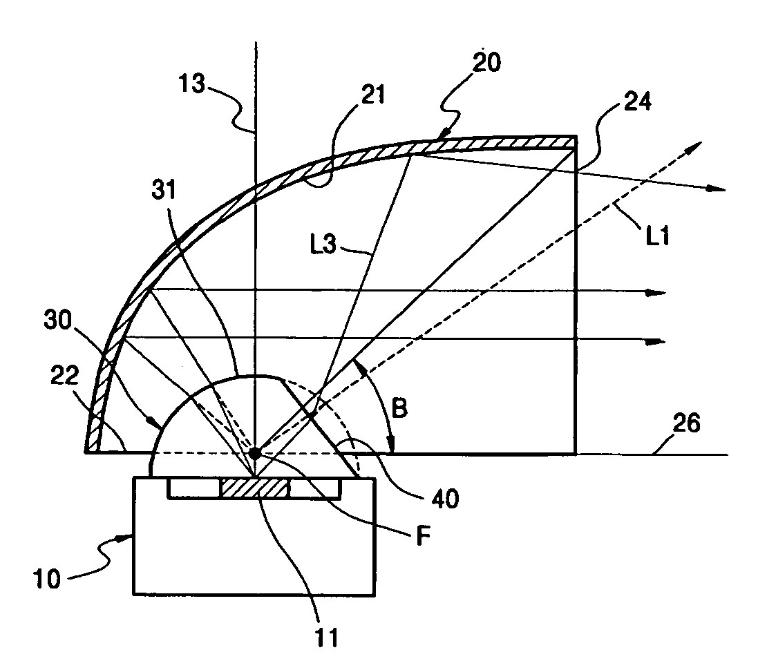
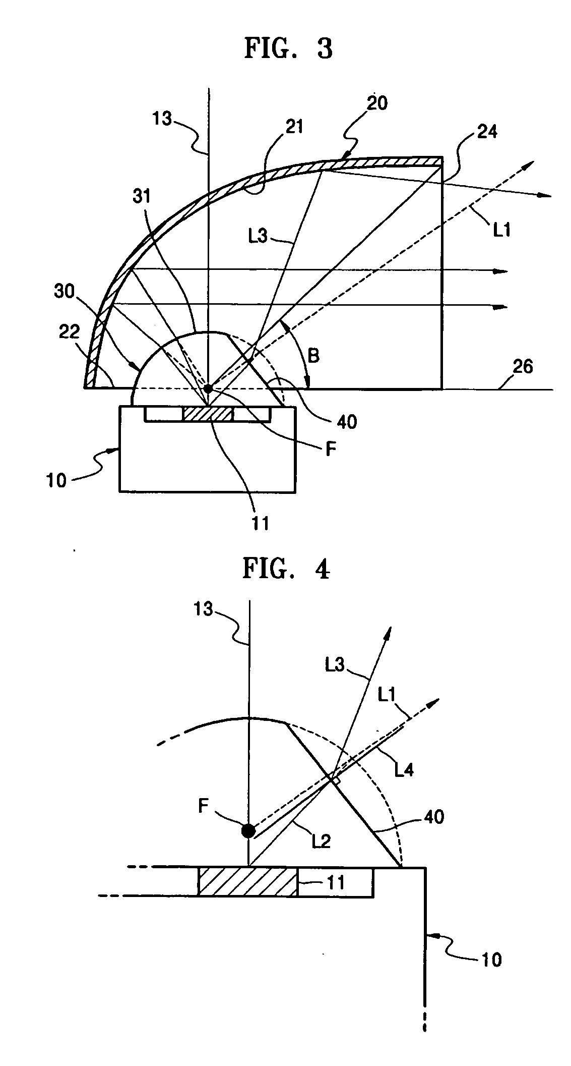
[0021]FIG. 3 illustrates an illumination unit according to an embodiment of the present general inventive concept. Referring to FIG. 3, the illuminating unit includes a light source 10 and a reflector 20. The reflector 20 includes a reflecting surface 21, an incident portion 22, and an exit portion 24. The incident portion 22 and the exit portion 24 face the reflecting surface 21 from different directions and intersect with each other. The reflecting surface 21 has a parabolic shape, which can be an aspherical surface with a conic coefficient K ranging from −0.4 to −2.5, and possibly from −0.7 to −1.6. The conic coefficient...


PUM


Abstract

An illuminating unit includes a reflector including a parabolic reflecting surface and an incident portion and an exit portion intersecting with each other a light source to emit a beam onto the reflecting surface through the incident portion, a light source deviation compensator disposed between the reflector and the light source to focus an image of the light source is focused to a focal point of the reflecting surface, and a light path changer to direct at least a portion of a beam with a radiation angle less than an angle of the exit portion toward the reflecting surface.

Description

CROSS-REFERENCE TO RELATED APPLICATIONS [0001] This application claims the priority under 35 U.S.C. §119 of Korean Patent Application No. 2004-94193, filed on Nov. 17, 2004, in the Korean Intellectual Property Office, the disclosure of which is incorporated herein in its entirety by reference. BACKGROUND OF THE INVENTION [0002] 1. Field of the Invention [0003] The present general inventive concept relates to an illuminating unit to emit a collimated beam and an image projection system including the same. [0004] 2. Description of the Related Art [0005] An illuminating unit employs various types of collimators including lenses to efficiently collimate a beam from a light source to a beam at a radiation angle to effectively illuminate an object. [0006] For example, an image projection system may include an illuminating unit illuminating a light modulator. When a large, bulky metal halide lamp or an ultrahigh-pressure mercury lamp is used as a light source in the illuminating unit, the ...

Claims


Application Information

Patent Timeline
Patent Type & Authority Applications(United States)
IPC IPC(8): F21V7/00
CPCF21V5/04F21V7/0016F21V13/04F21Y2101/02G02B27/0994H04N9/315G02B19/0066G02B19/0028G02B19/0061Y10S362/80F21Y2115/10G03B21/20
Inventor LEE, KYE-HOONKIM, DAE-SIKKIM, SU-GUN
Owner SAMSUNG ELECTRONICS CO LTD
Why Eureka
Try Eureka