Automatic pipette identification and detipping

a technology of automatic identification and pipette, applied in the field of pipettes, can solve the problems of preventing accurate fluid aspiration and dispensing, difficult to remove all contaminants, and expensive and time-consuming tip washing, and achieve the effects of facilitating the removal of the tip

Inactive Publication Date: 2006-05-18
VISTABLAB TECH LLC
View PDF98 Cites 3 Cited by
  • Summary
  • Abstract
  • Description
  • Claims
  • Application Information

AI Technical Summary

Benefits of technology

[0009] More specifically, the invention provides a mechanism for facilitating the removal of a tip from a pipette nozzle which includes a spring loaded ejector sleeve through which the nozzle passes, the sleeve terminating near the end of the nozzle to which the tip is mounted when the sleeve is in a normal position, the sleeve being moved away from the end of the nozzle against the spring load when the tip is mounted to the nozzle. The sleeve includes a first latch portion which mates with a second latch portion of the pipette when the sleeve is in a retracted position to which it is moved when a tip is properly mounted to the nozzle to hold the sleeve in the retracted position against the spring load, a third latch portion being provided which is operable to unmate the first and second latch portions, freeing the sleeve to return in response to the spring load to its normal position. The sleeve engages the tip before reaching the normal position to facilitate removal of the tip. The tip removal mechanism may include an overforce mechanism operable to supplement the spring load in moving the sleeve to its normal position against a stuck tip to further facilitate removal of the tip. For one embodiment, the first latch portion is a keyhole slot formed in the sleeve, the second latch portion is a detent having a large portion which fits in an enlarged portion of the slot when the sleeve is in its retracted position and a small portion sized to fit in a narrow portion of the slot, the narrow portion being adjacent to the detent except when the sleeve is in the retracted position. For this embodiment, the third latch portion is a button operable for moving the small portion of the detent into the slot to unlatch the sleeve. For this embodiment, the detent may be spring-biased to move the large portion of the detent into the slot. For another embodiment, the first latch portion is a projection at a proximal end of the sleeve, the second latch portion is a mating lip on a latch plate biased to have the lip engage the projection when the sleeve is in its retracted position and the third latch portion is a portion of the latch plate which is manually operable to move the plate against its bias to move the lip away from the projection, permitting the sleeve to return to its normal position. For this embodiment, an angled surface on the plate may be provided which is positioned to engage an angled surface associated with the sleeve when the latch plate is moved beyond the point where the lip no longer engages the projection, the interaction of the two angled surfaces supplementing the spring load in moving the sleeve to its normal position against a stuck tip to further facilitate removal of the tip.

Problems solved by technology

While it is possible to wash a pipette tip between aspirations in order to reduce or eliminate such contamination, and for some pipette systems, particularly those utilizing fluid displacement, this is frequently done, washing the tips is expensive and time-consuming, and it is frequently difficult to remove all contaminants.
However, when a pipette tip is mounted to the nozzle, it is important that the tip be mounted with sufficient force to seal the nozzle so that fluid being aspirated and dispensed does not leak around the tip-nozzle junction, thereby preventing accurate quantities of fluid from being aspirated and dispensed, and the tip must be mounted with sufficient force to prevent the tip from falling off.
However, if the tip is mounted with too much force, it can become difficult to remove the tip from the nozzle after use, resulting in significant strain on the operators hand.
For this and other reasons, an operator working in a laboratory or other facility where large numbers of tips are replaced each day may experience repetitive stress injuries with current pipette designs as a result of repeated tip removals.
Thus, while for an illustrative embodiment, only two pounds of force may be required to properly mount a tip to the nozzle, operators may inadvertently be applying 10 to 15 pounds of force in mounting the nozzle, making nozzle removal far more difficult than necessary.
However, without tactile guidance, an operator might overcompensate for this problem and not properly mount a nozzle.
Further, while some tip removal mechanisms have existed for pipettes in the past, these have generally been manually operated and, since they have generally not controlled tip mounting force, they have frequently required that substantial force be applied by, for example, the operator's thumb to successfully effect tip removal.
This operation is therefore another potential cause of repetitive stress injuries.
Alternatively, such tip removal schemes have been motor driven, increasing the size, cost and complexity of the pipette.
A related problem is that there are a variety of tips available for use with a given pipette and the pipette volume settings, particularly where these settings are automatically performed, need to be slightly adjusted for some tips to obtain the desired volumes of aspirated and / or dispensed fluid.
While provision may be made for the user to input information on the tip being used either on the pipette or on a processor used therewith, this can be burdensome for the operator where a large number of pipetting operations are being performed.
It also provides a source of pipetting error where the operator either forgets to identify a special tip used for a given operation or makes an erroneous entry, either because the operator doesn't know the tip used or enters tip information incorrectly.
It is also possible that the operator may select the wrong tip for a particular pipetting operation.

Method used


Image

  • Automatic pipette identification and detipping
  • Automatic pipette identification and detipping
  • Automatic pipette identification and detipping

Examples


Embodiment Construction

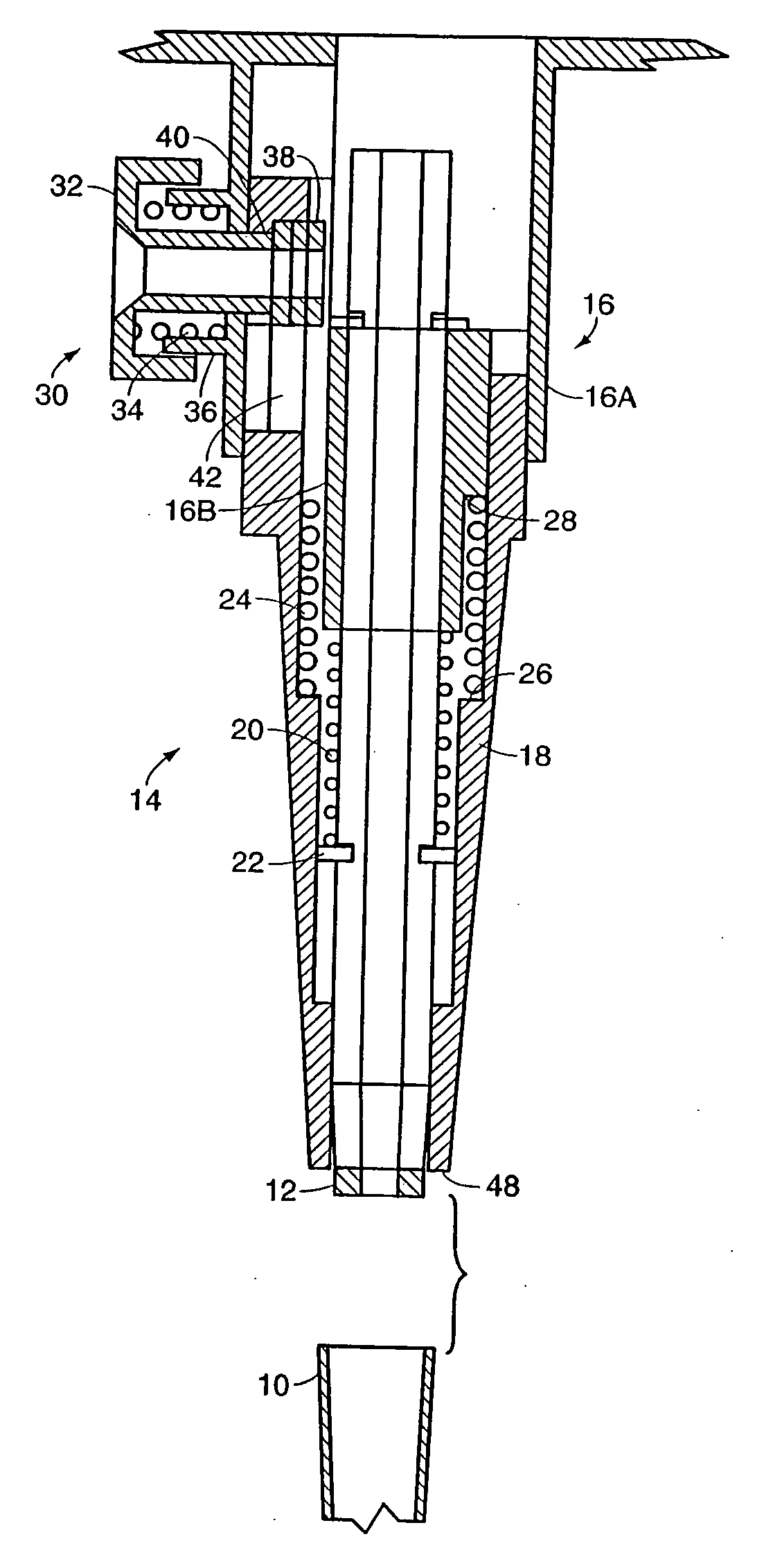
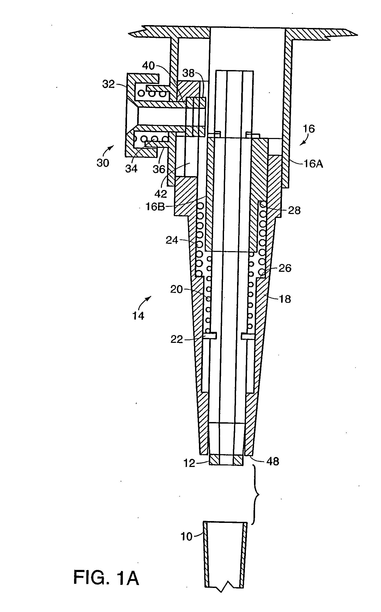
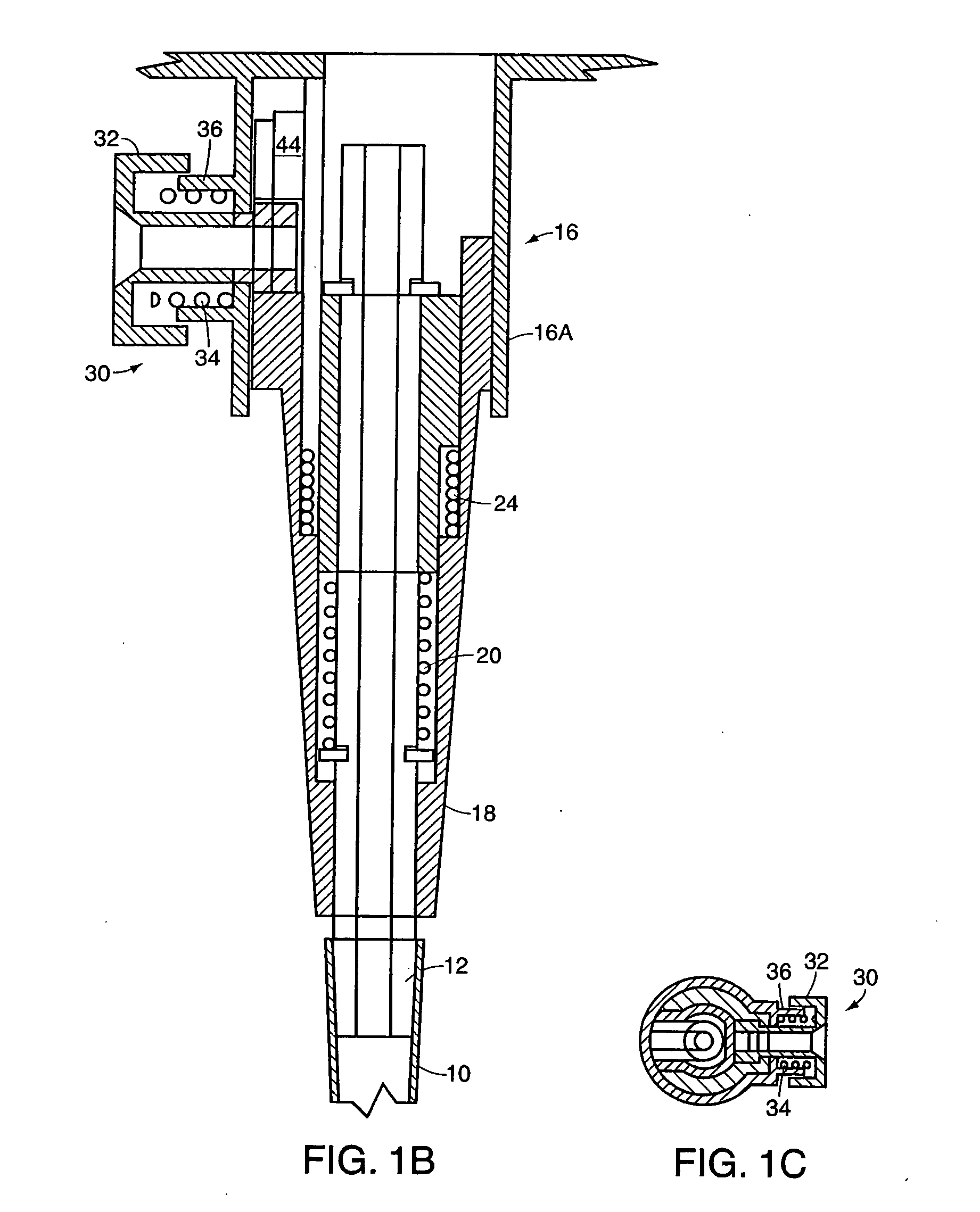
[0021] Referring to FIGS. 1A-1C, a first embodiment of the invention is shown wherein a tip 10 is mounted to a nozzle 12 which is part of a nozzle assembly 14. Assembly 14 includes a housing 16 having an outer sleeve 16A and an inner sleeve 16B. An ejector sleeve 18 surrounds nozzle 12, extending to a point near the distal end of the nozzle to which tip 10 is mounted, and fits at its proximal end between sleeves 16A and 16B of housing 16. Nozzle 12 is spring biased to the released position shown in FIG. 1A by a compression spring 20 extending between ring 22 fixed to nozzle 12 and the end of housing sleeve 16B. Ejector sleeve 18 is also spring biased to the released position of FIG. 1A by a compression spring 24 extending between an interior shoulder 26 of sleeve 18 and a shoulder 28 on inner housing sleeve 16B. In order for nozzle 12 to be movable as discussed herein, a flexible connection, for example a flexible hose, should be provided connecting the nozzle to its drive piston or...


PUM

PropertyMeasurementUnit
forceaaaaaaaaaa
distanceaaaaaaaaaa
movementaaaaaaaaaa

Abstract

Mechanisms are provided for automatically removing tips from a pipette nozzle and / or for detecting the type of tip mounted to the nozzle. For detipping, mechanical energy is stored when the tip is mounted to the nozzle and is released when the tip is to be removed to facilitate removal thereof. A mechanism is preferably provided which limits the force with which the tip is mounted to the nozzle and an overforce mechanism may be provided to facilitate removal of a stuck tip. For detecting tip type, each tip type has a different base configuration which results in a different relative displacement between the nozzle and a surrounding component as a result of the tip contacting both during tip mounting, the difference in relative displacement being detected to identify tip type.

Description

RELATED APPLICATIONS [0001] This application is a continuation of U.S. patent application Ser. No. 10 / 612,252, filed Jul. 1, 2003, which is a division of U.S. patent application Ser. No. 09 / 873,842, filed Jun. 4, 2001, which claims priority from U.S. provisional application Ser. No. 60 / 214,206 filed Jun. 26, 2000.FIELD OF THE INVENTION [0002] This invention relates to pipettes, and more particularly to pipettes having automatic mechanisms for identifying and / or removing tips. BACKGROUND OF THE INVENTION [0003] Pipettes are commonly utilized to aspirate a fluid from one container or other source and to dispense the fluid to a second container or other receptacle. Since the fluid being aspirated and dispensed is frequently analyzed or otherwise tested after being dispensed, and in order for such testing or analysis to be accurate, it is important that a sample not be contaminated by fluid from a prior aspirated sample. While it is possible to wash a pipette tip between aspirations in ...

Claims


Application Information

Patent Timeline
Patent Type & Authority Applications(United States)
IPC IPC(8): B01L3/02G01N1/00G01N35/10
CPCB01L3/0279B01L2200/143B01L2300/021Y10T436/2575G01N2035/0493G01N2035/103G01N35/10
Inventor CRONENBERG, RICHARD A.
Owner VISTABLAB TECH LLC
Why Eureka
Try Eureka