
Syringe, cap and method of producing prefilled syringe

a syringe and cap technology, applied in the direction of intravenous devices, infusion needles, other medical devices, etc., can solve the problems of inability to reliably connect, inconvenient assembly, and inability to relatively move along the axial direction of the male connector, etc., to achieve easy and assured connection

Inactive Publication Date: 2006-05-18
TERUMO KK
View PDF11 Cites 60 Cited by
  • Summary
  • Abstract
  • Description
  • Claims
  • Application Information

AI Technical Summary

Benefits of technology

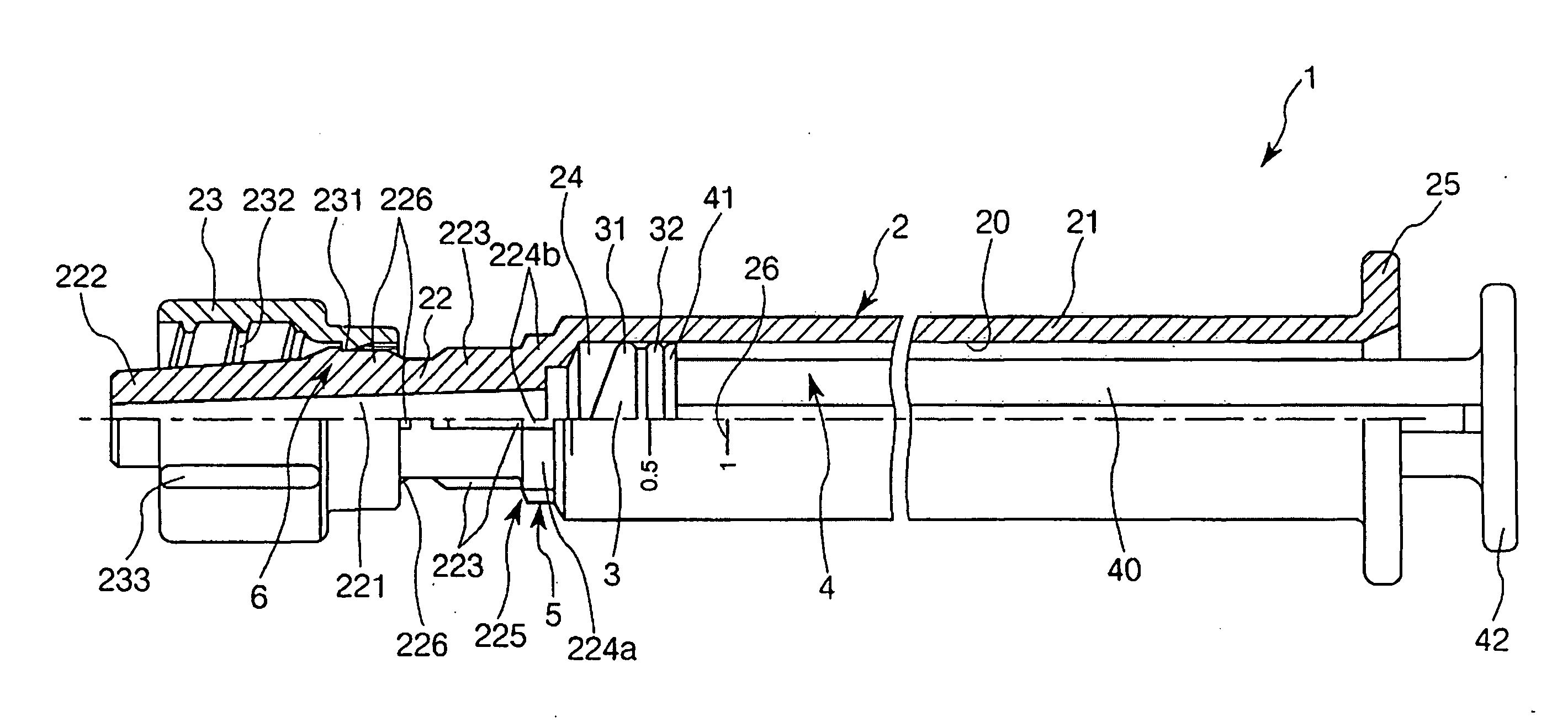
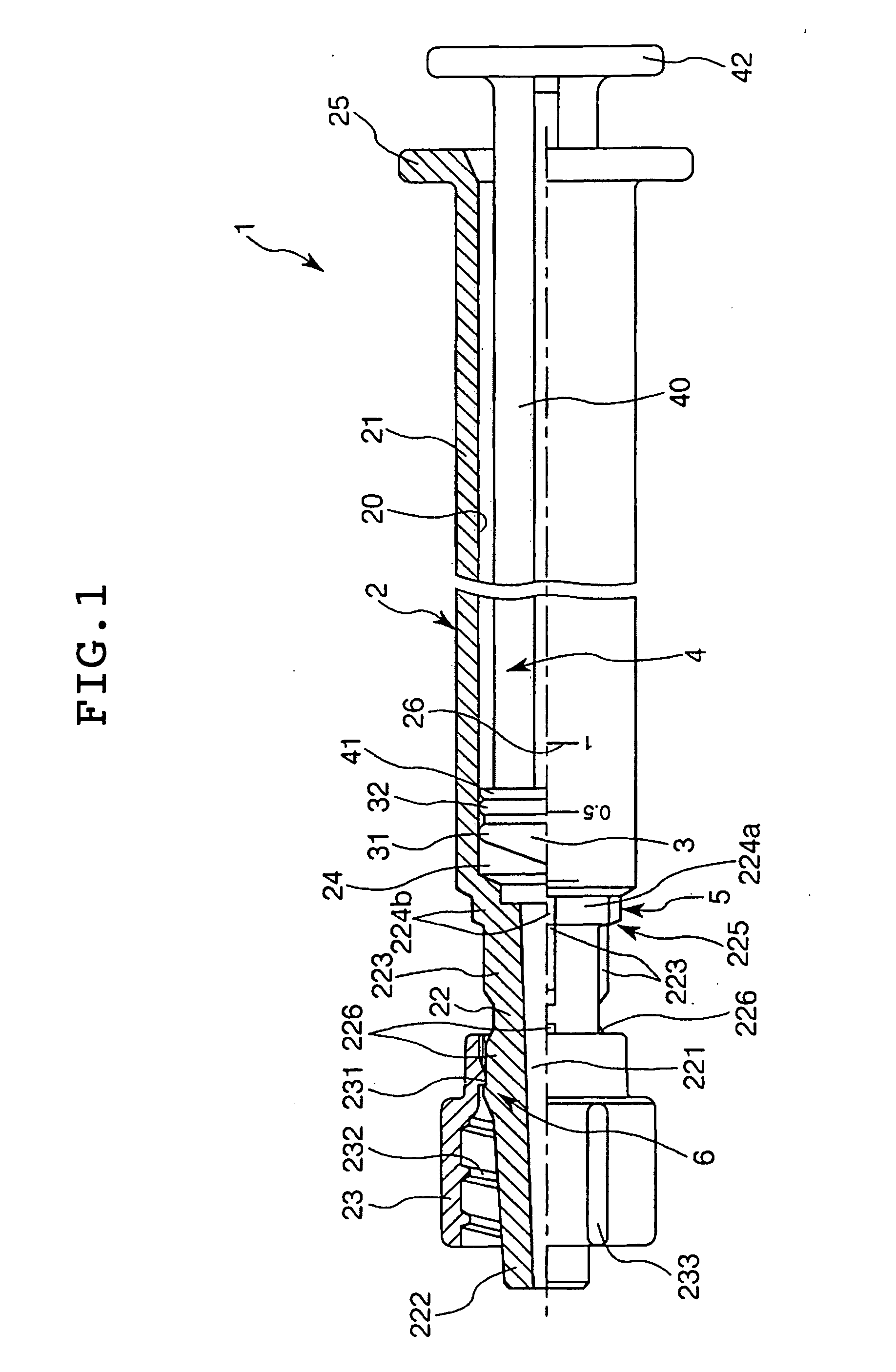
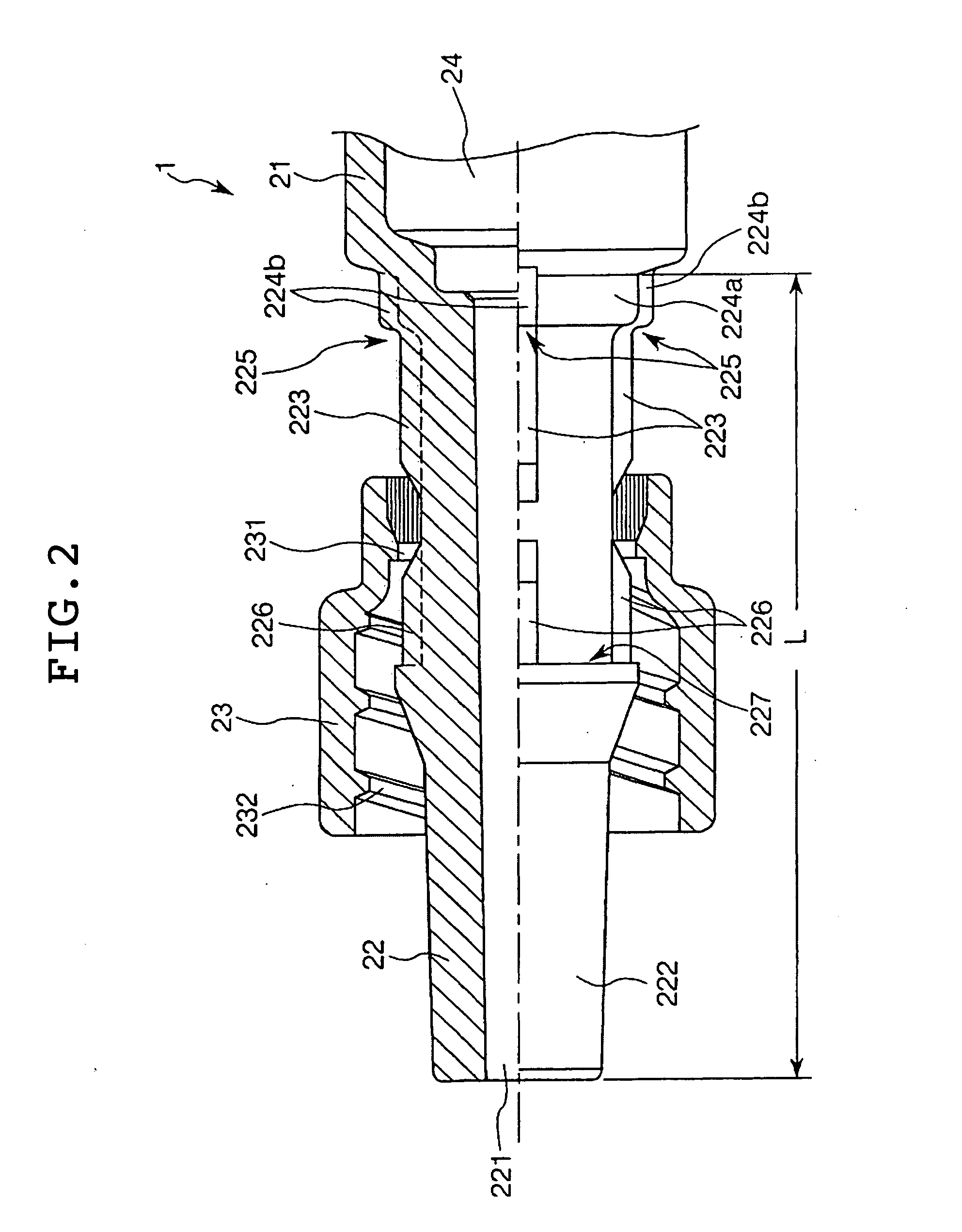
[0015] It is a first object of the present invention to provide a syringe which enables easy and assured connection thereof with both a female connector having a female-side screw engagement portion on its outer peripheral surface and a female connector not having the female-side screw engagement portion.
[0037] It is a second object of the present invention to provide a cap which is capable of being mounted to a prefilled syringe having a lock adapter and which makes it possible to keep in a sterile condition the surroundings of a mouth portion of a syringe outer hollow cylinder after a sterilizing treatment. It is also the second object of the present invention to provide a method of producing a prefilled syringe in which the cap is used.

Problems solved by technology

However, in the female connector configured as above, the connection member is fixed and, therefore, cannot be relatively moved along the axial direction of the male connector (see FIG. 1 of Japanese Utility Model Publication No.
Therefore, when it is intended to connect a female connector not formed with any screw portion on its outer peripheral surface to the male taper portion, the connection member obstructs the connecting operation, so that the connection cannot be performed assuredly.
In such a male connector, however, the connection member cannot be relatively moved along the axial direction of the male connector unless the predetermined operation is carried out, and, therefore, it is extremely intricate to expose the male taper portion.
Therefore, at the time of connecting a female connector not formed with any screw groove in its outer peripheral surface to the male taper portion, the connection member may move along the axial direction of the female connector, thereby obstructing the connecting operation.
Meanwhile, the prefilled syringe provided with the lock adapter has had the problem that there is no cap for hermetically closing (sealing) the liquid discharge portion.
Therefore, at the time of connecting the prefilled syringe to the connector, the liquid discharge portion would be exposed to the atmosphere (air) for a long time, whereby the liquid discharge portion may be polluted with bacteria.

Method used


Image

  • Syringe, cap and method of producing prefilled syringe
  • Syringe, cap and method of producing prefilled syringe
  • Syringe, cap and method of producing prefilled syringe

Examples


first embodiment

[0201]FIG. 12 is a side view of the prefilled syringe with the cap shown in FIG. 10 mounted thereto.

[0202] The steps for producing the prefilled syringe 1 will be described below.

[0203] [A1] Sterilizing Step (First Step)

[0204] First, an outer hollow cylinder 2 and a cap 7 are prepared, and are sterilized respectively.

[0205] Incidentally, the sterilization in this instance is not particularly limited, and may be carried out by, for example, autoclave sterilization, gas sterilization using a sterilizing gas such as hydrogen peroxide, EOG, etc., radiation sterilization utilizing irradiation with radioactive rays such as γ-rays, electron beams, etc., or the like. Now, individual cases of using these sterilizing methods will be described below.

[0206] [A1-1] Step Using Autoclave Sterilization (Autoclave Sterilization Step)

[0207] The outer hollow cylinder 2 and the cap 7 are placed in an autoclave sterilization system. In this condition, high-pressure water vapor R is supplied into t...

second embodiment

[0221] Now, a second embodiment of the method of producing a prefilled syringe will be described below. The following description will be centered on differences from the first embodiment above, and description of the same points in the first embodiments will be omitted.

[0222] The second embodiment is the same as the first embodiment, except that the order of the step of sterilizing the outer hollow cylinder 2 and the cap 7 (sterilising step) and the step of mounting the cap 7 to the mouth portion 22 (capping step) is different.

[0223] [B1] Capping Step (First Step)

[0224] First, the outer hollow cylinder 2 and the cap 7 are prepared, and the cap 7 is mounted onto the mouth portion 22 of the outer hollow cylinder 2 (see FIG. 11).

[0225] [B2] Sterilizing Step (Second Step)

[0226] In this condition (the capped condition), the outer hollow cylinder 2 (inclusive of the cap 7) is sterilized.

[0227] Incidentally, the sterilization in this instance is conducted by, for example, radiation ...


PUM


Abstract

A first female connector and a second female connector that has on its outer periphery a screw portion engaging a female screw can be alternatively connected to the top of a syringe. A mouth portion with a smaller diameter than a barrel portion of an outer hollow-cylinder main body is provided at the top of an outer hollow-cylinder. A lock adapter is provided on the outer periphery of the mouth portion. The lock adapter is rotatable about the mouth portion and axially movable in an axial direction of the mouth portion. The lock adapter can be moved to a position at the base of the mouth portion where the operation of fitting a male taper portion formed at the top of the mouth portion into a bore portion of the first female connector is not interrupted. The lock adapter can be fixed to the mouth portion at the position to which the adapter is moved.

Description

TECHNICAL FIELD [0001] The present invention relates to a syringe, a cap, and a method of producing a prefilled syringe provided with said cap. BACKGROUND ART [0002] In medical sites, there are cases where various medical implements such as syringes, injection needles, catheters, and infusion sets are used in connection with each other. [0003] Methods for the connection include, for example, a method in which a male taper portion possessed by a male connector provided at an end portion of one medical implement is fitted into a bore portion of a female connector provided at an end portion of the other medical implement. [0004] In addition, the female connectors include one which is provided in its outer peripheral surface with a screw groove (a female-side screw engagement portion), and, correspondingly, the male connectors include one which is provided, at the outer peripheral portion of the male taper portion, with a connection member formed with a screw thread (a male-side screw e...

Claims


Application Information

Patent Timeline
Patent Type & Authority Applications(United States)
IPC IPC(8): A61M5/00A61M5/32A61M5/31A61M5/34A61M39/10A61M39/20
CPCA61M5/344A61M5/347A61M39/1011A61M39/20A61M2005/3104
Inventor KITO, HIDEAKITACHIKAWA, KOUICHI
Owner TERUMO KK
Learn More