Baluster assembly

a technology of assembly and clusters, applied in the direction of clusters, building components, pillars, etc., can solve the problems of relative heavyness and relatively high production cost, and achieve the effect of convenient installation

Inactive Publication Date: 2006-05-25
CHUNG MIN JU
View PDF5 Cites 12 Cited by
  • Summary
  • Abstract
  • Description
  • Claims
  • Application Information

AI Technical Summary

Benefits of technology

[0005] The object of the present invention is to provide a baluster assembly which is relatively light and which is easy to install.

Problems solved by technology

Since the baluster is solid, it is relatively heavy.
Furthermore, since the lower and upper anchors 2, 3 are connected to the ends of the post body 1 by forging, the production cost is relatively high.

Method used


Image

  • Baluster assembly
  • Baluster assembly
  • Baluster assembly

Examples


Embodiment Construction

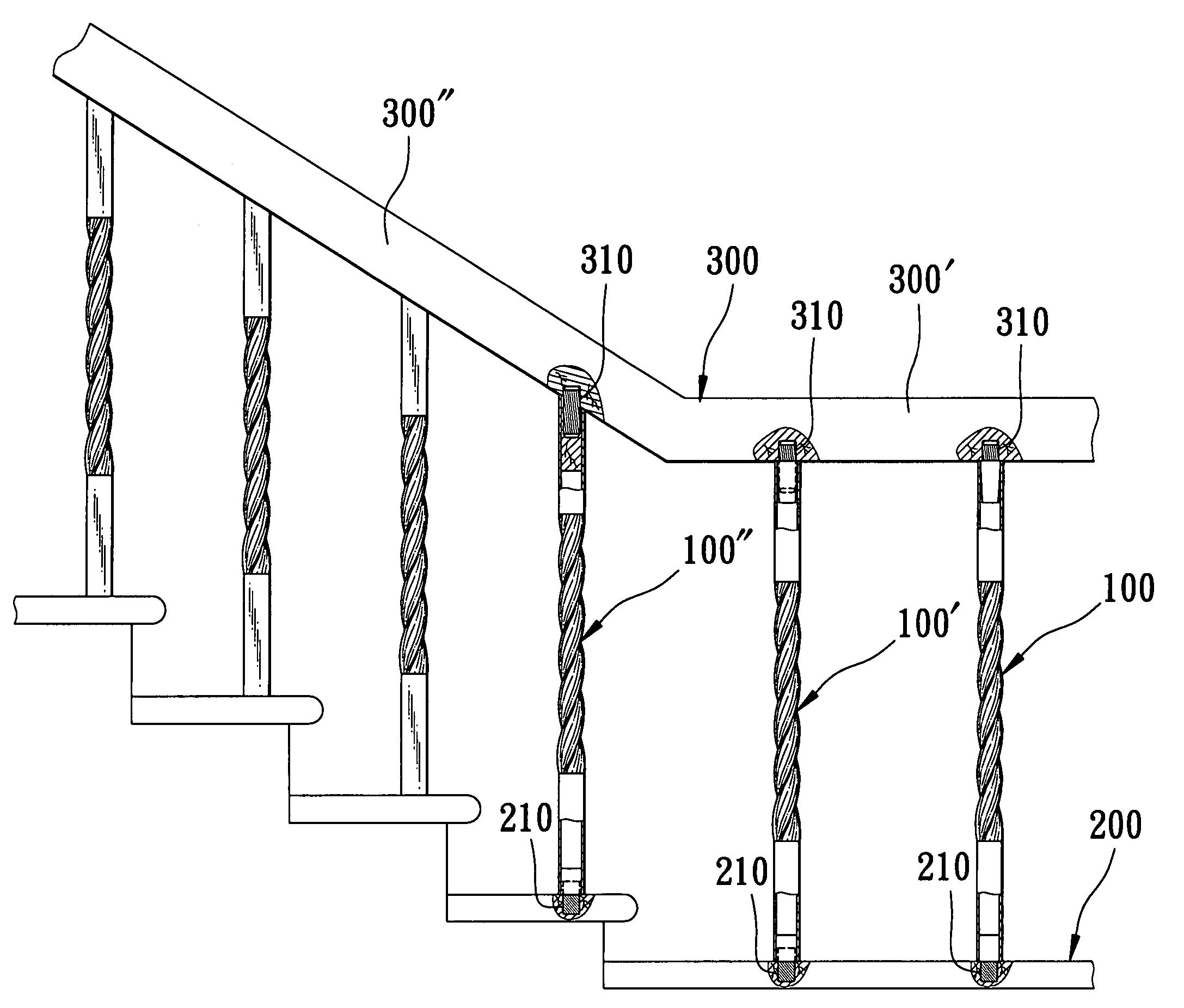
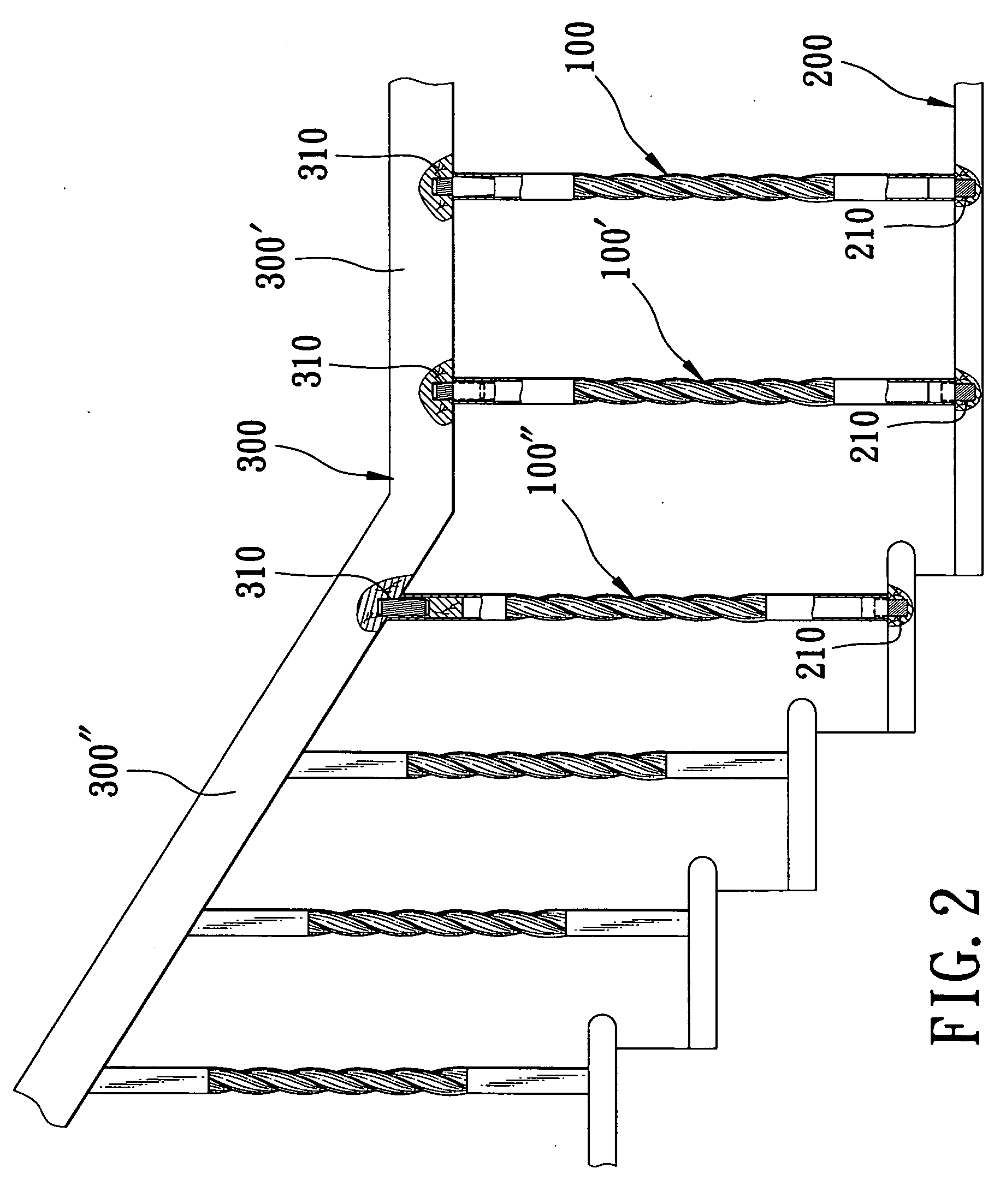
[0015] Referring to FIG. 2, the first, second and third preferred embodiments of a baluster assembly 100, 100′, 100″ according to this invention is shown to be installed between a base 200 and a handrail 300. The base 200 is provided with a plurality of holes 210, and the handrail 300 is provided with a plurality of holes 310 corresponding to the holes 210 in the base 200.

[0016] Referring to FIG. 3, the first preferred embodiment of the baluster assembly 100 is shown to include a hollow post 10, a top connecting element 30 mounted on top of the hollow post 10, and a bottom connecting element 20 mounted on the bottom of the hollow post 10.

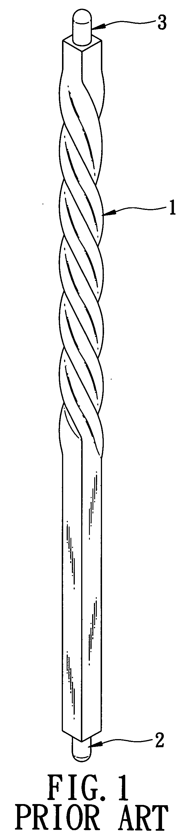
[0017] The hollow post 10 is made from a metal tube, has a top end section 112, a bottom end section 111 opposite to the top end section 112, and an intermediate patterned section 113 extending between the top and bottom end sections 112, 111 along a longitudinal axis (L). The first preferred embodiment of the baluster assembly 100 is suitable for...


PUM


Abstract

A baluster assembly mountable between a base and a handrail includes a hollow post, a top connecting element, and a bottom connecting element. The hollow post has a pair of opposite end sections, and an intermediate patterned section between the end sections. Each of the end sections defines a hole. The top connecting element has a first plug portion fitted into the hole of one of the end sections, and a first anchor portion extending upward from the first plug portion and connected to the handrail. The bottom connecting element has a second plug portion fitted into the hole of the other one of the end sections, and a second anchor portion connected to the base.

Description

BACKGROUND OF THE INVENTION [0001] 1. Field of the Invention [0002] The invention relates to a baluster assembly, more particularly to a baluster assembly which is relatively light, and which is easy to install. [0003] 2. Description of the Related Art [0004] Referring to FIG. 1, a conventional baluster is formed with a solid configuration, and includes a post body 1, and lower and upper anchors 2, 3 forged directly onto two ends of the post body 1, respectively. Since the baluster is solid, it is relatively heavy. Furthermore, since the lower and upper anchors 2, 3 are connected to the ends of the post body 1 by forging, the production cost is relatively high. SUMMARY OF THE INVENTION [0005] The object of the present invention is to provide a baluster assembly which is relatively light and which is easy to install. [0006] Accordingly, the baluster assembly of this invention is mountable between a base and a handrail, and includes a hollow post, a top connecting element, and a botto...

Claims


Application Information

Patent Timeline
Patent Type & Authority Applications(United States)
IPC IPC(8): E04C3/30
CPCE04F11/1842E04F11/1812E04F11/1846E04F2011/1821E04F2011/1827
Inventor CHUNG, MIN-JU
Owner CHUNG MIN JU
Why Eureka
Try Eureka