Micromechanical rotational rate sensor

a technology of rotational rate sensor and micro-mechanical structure, which is applied in the direction of acceleration measurement using interia force, turn-sensitive devices, instruments, etc., can solve the problems of insufficient robustness of the structure, the sensitivity of the structure with respect to interference acceleration, and the known rotational rate sensor may be particularly sensitive to this kind of interference acceleration, so as to reduce the sensitivity to interference acceleration, the effect of reducing the acceleration of interference in particular in the vehicl

Inactive Publication Date: 2006-05-25
ROBERT BOSCH GMBH
View PDF1 Cites 10 Cited by
  • Summary
  • Abstract
  • Description
  • Claims
  • Application Information

AI Technical Summary

Benefits of technology

[0012] The micromechanical rotational rate sensor according to an exemplary embodiment of the present invention thus may have greatly improved sensitivity to interference and cross sensitivity, robustness and resolution range (driving dynamics range). This may be achieved by the possibility of selecting a high operating frequency and by the special symmetrical designs of the sensor mass elements.
[0014] In the case of the structure described here, at the same time, the tuning fork principle and the inverse tuning fork principle play a role. The structure described may be designed for operating frequencies >10 kHz. This may lead to a further reduction of the sensitivity to interference of the sensor elements in the situation of their use in the automobile field. Interference accelerations in particular in a vehicle may be reduced in this frequency range compared to the frequency range in use up to now, of typically 1.5 kHz to 6 kHz. The selection of the operating frequency furthermore may lead to substantially more robust sensor structures having an increased falling protection. A suspension on numerous folded spring elements may also contribute to robustness.

Problems solved by technology

One disadvantage of the known rotational rate sensors is the sensitivity of the structures with respect to interference accelerations, particularly with respect to angular accelerations about the sensitive axis, as well as with respect to the insufficient robustness of the structures.
Therefore, the known rotational rate sensors may be particularly sensitive to this kind of interference acceleration.
The low working frequencies may also be a reason for the inadequate robustness of the rotational rate sensors, particularly as regards falling protection.

Method used


Image

  • Micromechanical rotational rate sensor
  • Micromechanical rotational rate sensor

Examples


Embodiment Construction

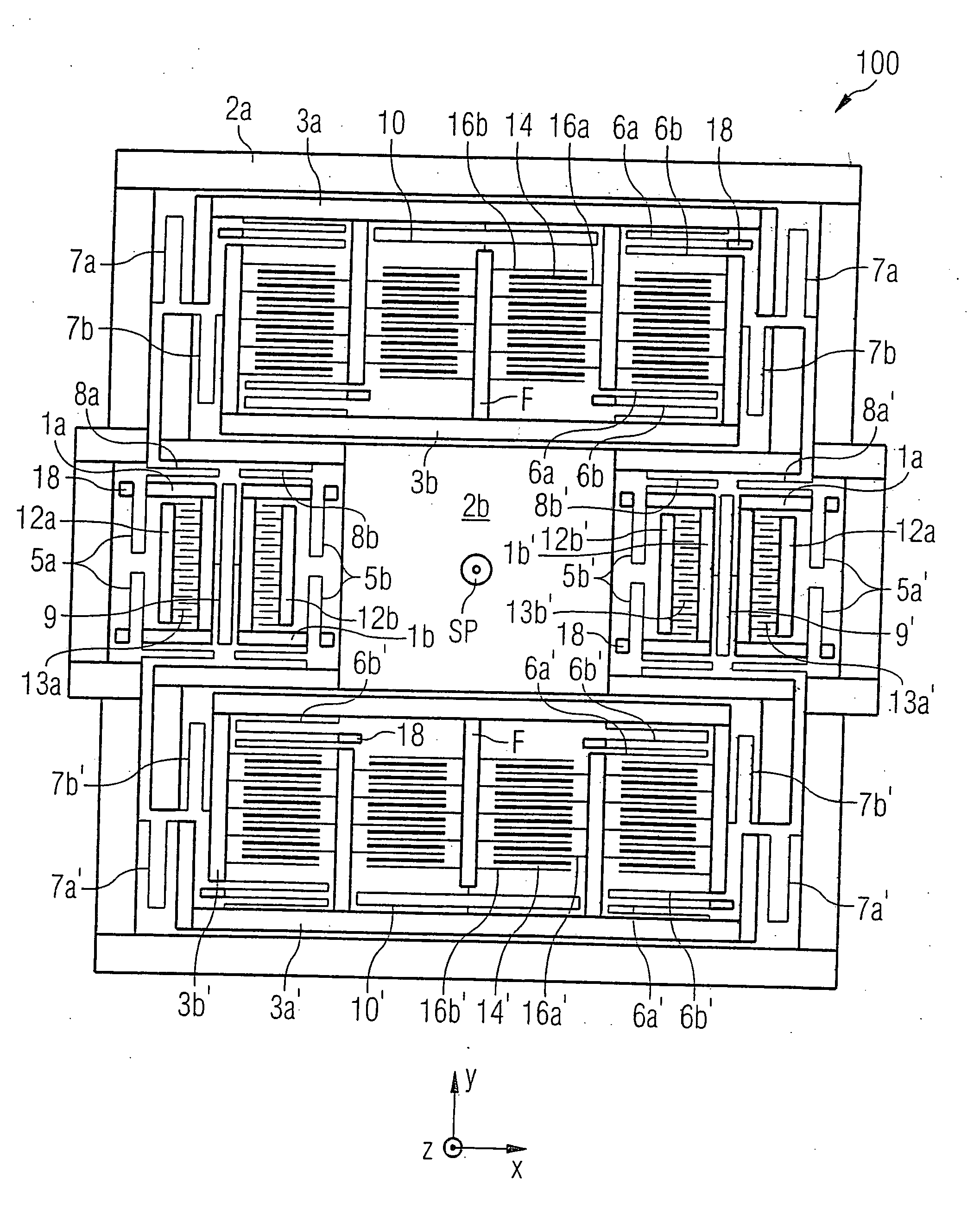
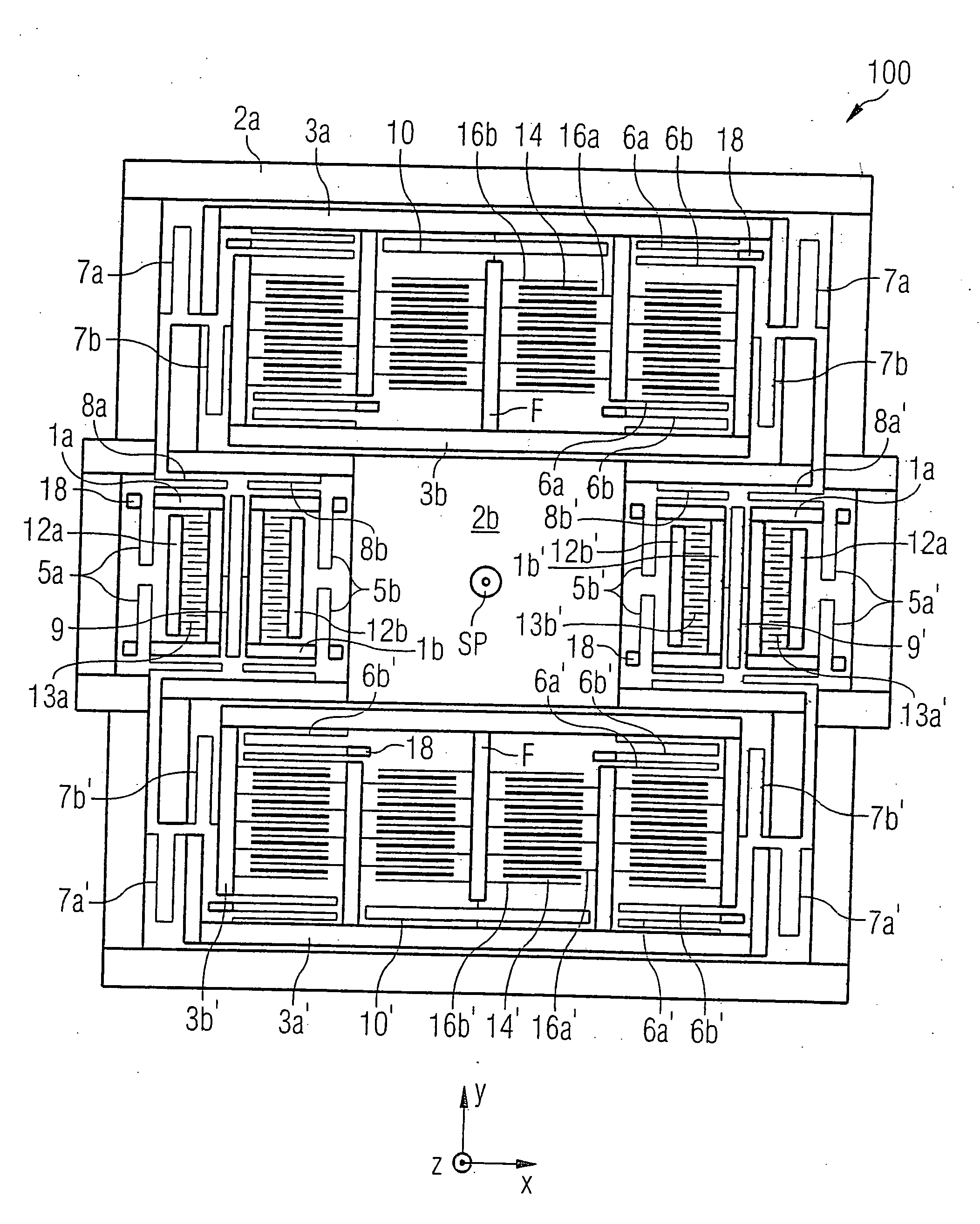
[0028] For reasons of clarity, not all elements in FIGURE 1 have been provided with reference numerals.

[0029] In FIGURE 1, 1a denotes a first activating mass element, 1a′ a second activating mass element, 1b a third activating mass element and 1b′ a fourth activating mass element. 2a is a first Coriolis mass element and 2b is a second Coriolis mass element. 3a denotes a first detecting mass element, 3a′ a second detecting mass element, 3b a third detecting mass element and 3b′ a fourth detecting mass element.

[0030] As may be seen in FIGURE 1, all the functional mass elements 1a, 1a′, 1b, 1b′, 2a, 2b, 3a, 3a′, 3b, 3b′ are situated symmetrically in such a manner that their center of gravity coincides at a common mass center of gravity SP, which lies at the center of the vibrating structure. All individual masses are suspended movably over substrate 100. Besides setting the common mass center of gravity, the selected symmetrical construction also assures nonsensitivity to process tol...


PUM


Abstract

An exemplary embodiment of the present invention creates a micromechanical rotational rate sensor having a first Coriolis mass element and a second Coriolis mass element which may be situated over a surface of a substrate. An exemplary embodiment of a micromechanical rotational rate sensor may have an activating device by which the first Coriolis mass element and the second Coriolis mass element are able to have vibrations activated along a first axis. An exemplary embodiment of a micromechanical rotational rate sensor may have a detection device by which deflections of the first Coriolis mass elements and of the second Coriolis element are able to be detected along a second axis, which is perpendicular to the first axis, on the basis of a correspondingly acting Coriolis force. The first axis and second axis may run parallel to the surface of the substrate. The detecting device may have a first detection mass device and a second detection mass device. The centers of gravity of the first Coriolis mass element, the second Coriolis mass element, the first detection mass device and the second detection mass device may coincide at a common mass center of gravity when they are at rest.

Description

CROSS-REFERENCE TO RELATED APPLICATION [0001] This application is a continuation of prior application U.S. Ser. No. 10 / 473,004 filed Apr. 2, 2004, which was a National Stage Application of PCT International Application No. PCT / DE02 / 03570.FIELD OF THE INVENTION [0002] The present invention relates to a micromechanical rotational rate sensor. BACKGROUND INFORMATION [0003] Rotational rate sensors in which a first and a second Coriolis element are arranged on the surface of a substrate are discussed in U.S. Pat. No. 5,728,936. The Coriolis elements may be induced to vibrate along a first axis. The deflections of the Coriolis elements due to a Coriolis force along a second axis, which is likewise parallel to the substrate, may be verified. [0004] German Patent No. 198 32 906 discusses a capacitive rotational rate sensor made up of a flexibly supported, mirror-symmetrically designed seismic mass, on which electrodes are fastened in a comb-like manner. At least two groups of comb-like coun...

Claims


Application Information

Patent Timeline
Patent Type & Authority Applications(United States)
IPC IPC(8): G01P15/08G01C19/56G01C19/5747
CPCG01C19/5747
Inventor WILLIG, RAINERTHOMAE, ANDREASKUHLMANN, BURKHARDHAUER, JOERGGOMEZ, UDO-MARTINGOETZ, SIEGBERTDOERING, CHRISTIANFEHRENBACH, MICHAELBAUER, WOLFRAMBISCHOF, UDONEUL, REINHARDFUNK, KARSTENLUTZ, MARKUSWUCHER, GERHARDFRANZ, JOCHEN
Owner ROBERT BOSCH GMBH
Why Eureka
Try Eureka