Spline drive fastener system

a technology of drive shaft and fastener, which is applied in the direction of screwdrivers, screws, fastening means, etc., can solve the problems of affecting the use of driver tools, affecting the safety of the driver tool, and the inability to drive the fastener further into the substrate or be removed from the substrate. , to achieve the effect of safe, efficient and effective engagement with the driver tool

Inactive Publication Date: 2006-05-25
HANDY & HARMAN
View PDF12 Cites 11 Cited by
  • Summary
  • Abstract
  • Description
  • Claims
  • Application Information

AI Technical Summary

Benefits of technology

[0010] An object of the invention is to provide a method of forming a drive engagement surface with a die which provides a strong contact interface between the drive engagement portion of the fastener head and the driver tool during installation of the fastener.
[0011] A further object of the invention is to provide a fastener with a drive engagement surface which provides safe, efficient, and effective engagement with a driver tool.

Problems solved by technology

The conventional fastener head and driving tool arrangement suffers from several drawbacks.
The disengagement process can result in the fastener head being stripped or damaged such that the fastener cannot be either driven further into the substrate or be removed from the substrate.
In addition, the disengagement often results in the tool suddenly losing contact with the fastener such that the tool user cannot maintain control of the tool and / or associated driving device.
For example, during construction, fasteners are often required to be used on portions of a structure which are not readily accessible.
These structural portions may be positioned in an elevated, partially occluded, overhead, and / or in an orientation relative to the fastener installer such that the tool / fastener alignment as well as the pressure between the tool and fastener cannot be consistently maintained.
This situation prevents a typical user from being able to apply as much force on the power driver as would be possible if the arm alignment was directly in front of the body center.
This often results in the fastener head being stripped and / or the tool becoming disengaged with the fastener.

Method used


Image

  • Spline drive fastener system
  • Spline drive fastener system
  • Spline drive fastener system

Examples


Embodiment Construction

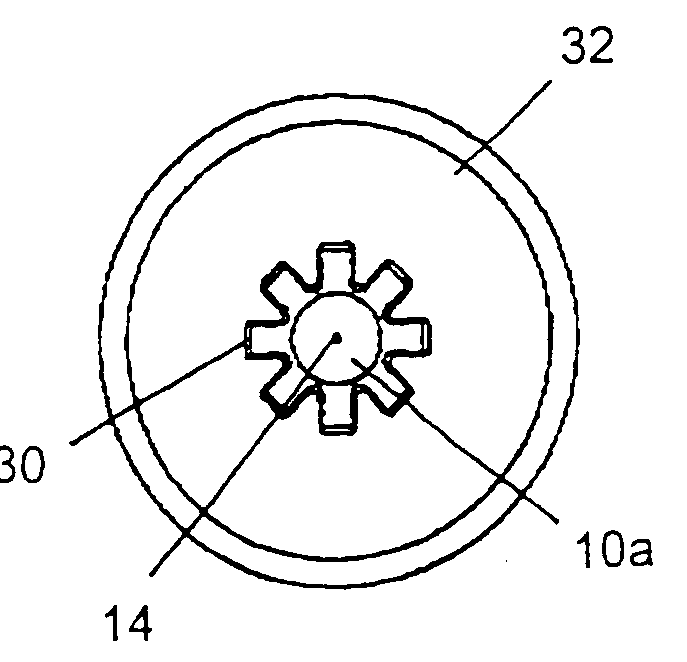
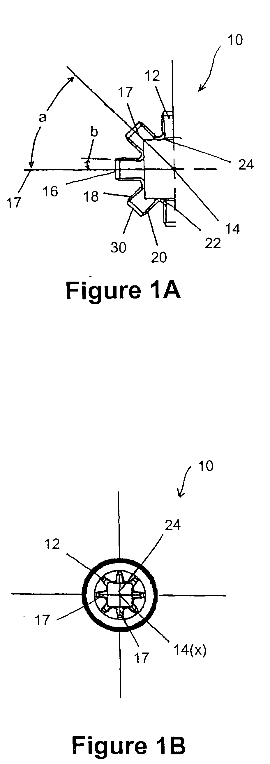
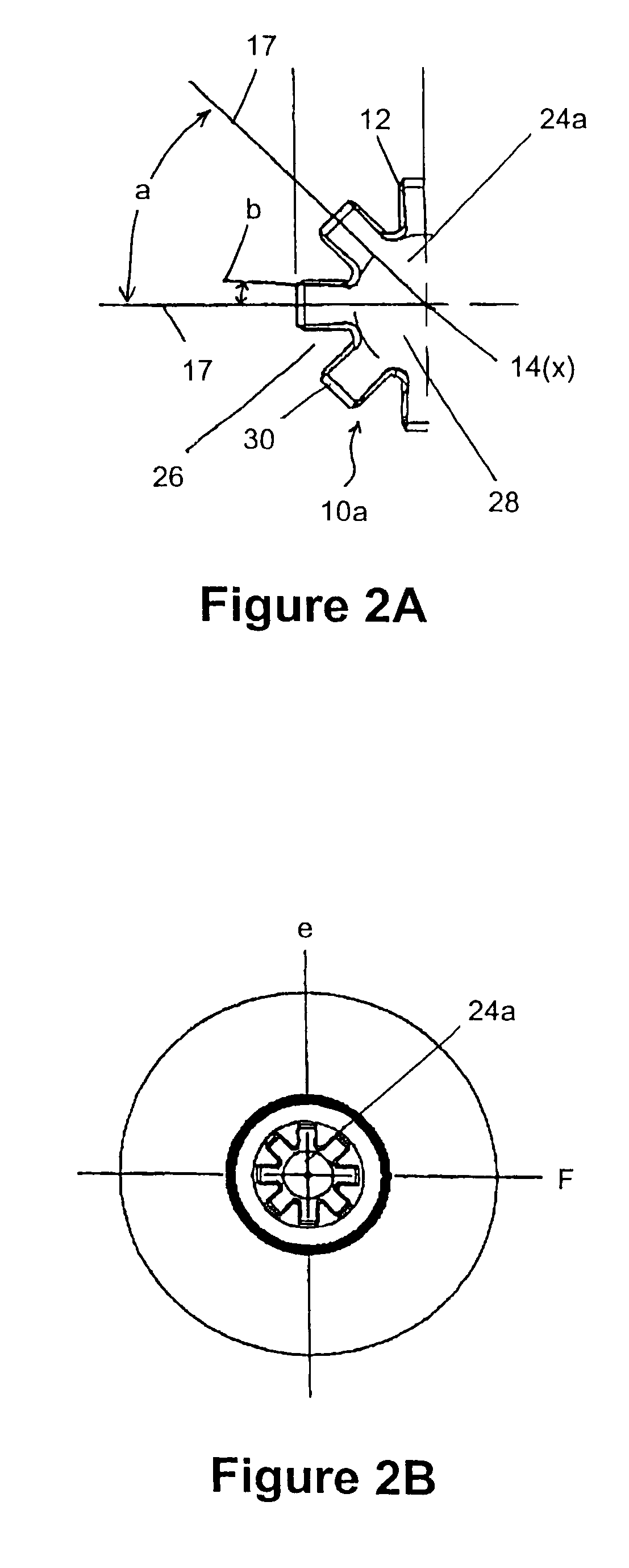
[0038] With reference to the drawings wherein like numerals represent like parts throughout the several figures, a fastener engagement surface formed in the head of a fastener in accordance with the present invention is generally designated by the numeral 10. The fastener engagement surface 10 includes, as partially shown in FIG. 1A and as shown in FIG. 1B, the walls of at least eight radial slots 12 spaced about a center axis 14 of the engagement surface 10.

[0039] In one embodiment of the present invention, each radial slot 12 includes a rear wall 16, a first side wall 18, and a second side wall 20. A radial slot center plane 17 extends from the center axis 14 of the engagement surface 10 through a point substantially equidistant from the positions where the rear wall 16 and the first side wall 18 intersect, and where the rear wall and the second side wall 20 intersect. The first side wall 18 of a first radial slot 12 and the second side wall 20 of a second adjacent radial slot 12...


PUM


Abstract

A spline drive fastener system involves a fastener wherein a drive engagement surface is formed in the head of the fastener. The drive engagement surface includes eight separate points of engagement. The points of engagement are arranged on eight radial slots formed by the central axis of the fastener head. A method of forming the drive engagement surface comprises forcing a punch against a fastener workpiece to form at least eight radial slots.

Description

CROSS-REFERENCE TO RELATED APPLICATION [0001] This application claims the priority of U.S. Application No. 60 / 630,451 filed on Nov. 23, 2004.FIELD OF THE INVENTION [0002] This invention relates generally to fasteners used in the construction arts, and in particular, to fasteners having drive surfaces. BACKGROUND OF THE INVENTION [0003] Commercial and residential structures are typically constructed with a variety of fastener types. Typically these fasteners have a head configured to receive a tool for the purpose of allowing the fastener to be driven into an appropriate substrate. Conventionally, the tool receiving portion of the fastener head includes recessed areas which form slots or cavities. The slots are generally either a single slot, formed across the surface of the head, or a pair of intersecting slots which form a cross. In some cases, the fastener head includes a cavity in the form of a square. [0004] Conventionally, a tool having a complementary shape to portions of the ...

Claims


Application Information

Patent Timeline
Patent Type & Authority Applications(United States)
IPC IPC(8): F16B23/00
CPCB25B15/005F16B23/003
Inventor BELINDA, RICHARD
Owner HANDY & HARMAN
Why Eureka
Try Eureka