
Deformity reduction instrument and method

a technology of deformity and instrument, applied in the field of surgical instruments, can solve the problems of current devices, extreme pain, debilitating pain, etc., and achieve the effect of convenient use and efficient treatmen

Inactive Publication Date: 2006-05-25
MEDICAL INNOVATORS
View PDF5 Cites 87 Cited by
  • Summary
  • Abstract
  • Description
  • Claims
  • Application Information

AI Technical Summary

Benefits of technology

[0008] The present invention advantageously provides instrumentation for rod reduction during orthopedic surgery that is efficient, convenient to use and provide for simultaneous manipulation of a rod and a spinal implant. In this regard, the apparatus has a shaft assembly and a lever assembly. The shaft assembly can include a shaft defining a proximal end, a distal end, a top portion, and a bottom portion, with the shaft further defining a first threaded portion. A gripper assembly may be coupled to the distal end of the shaft, with the gripper assembly being engageable with the bone fastener. The medical device may further provide

Problems solved by technology

Patients that suffer from such conditions usually experience extreme and debilitating pain, as well as diminished nerve function.
However, current devices work in only a single plane, which requires significantly more rod contouring in an effort to match two of the three planes prior to attempting reduction of the rod to the spinal implant or reduction of the spinal implant to join the rod.

Method used


Image

  • Deformity reduction instrument and method
  • Deformity reduction instrument and method
  • Deformity reduction instrument and method

Examples


Embodiment Construction

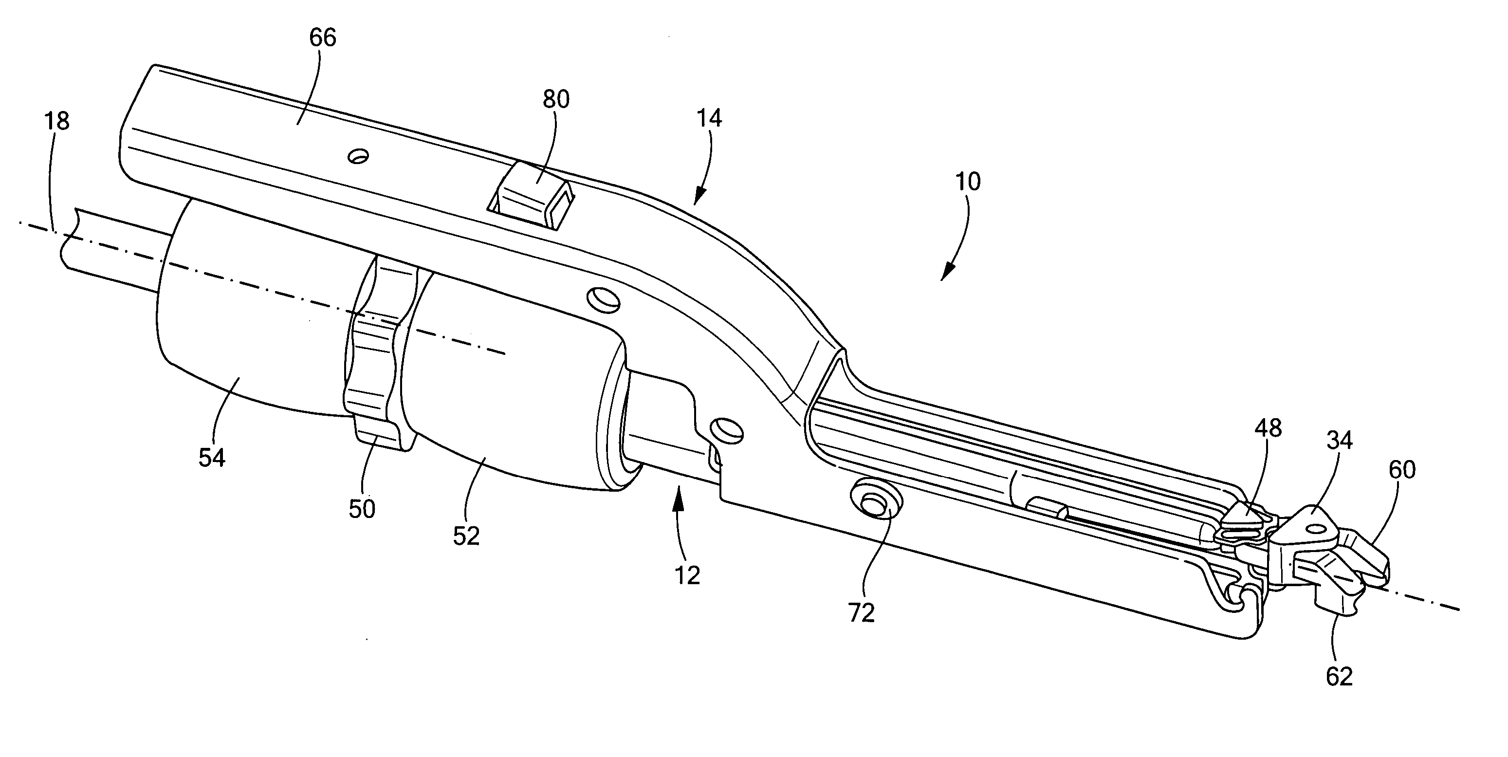
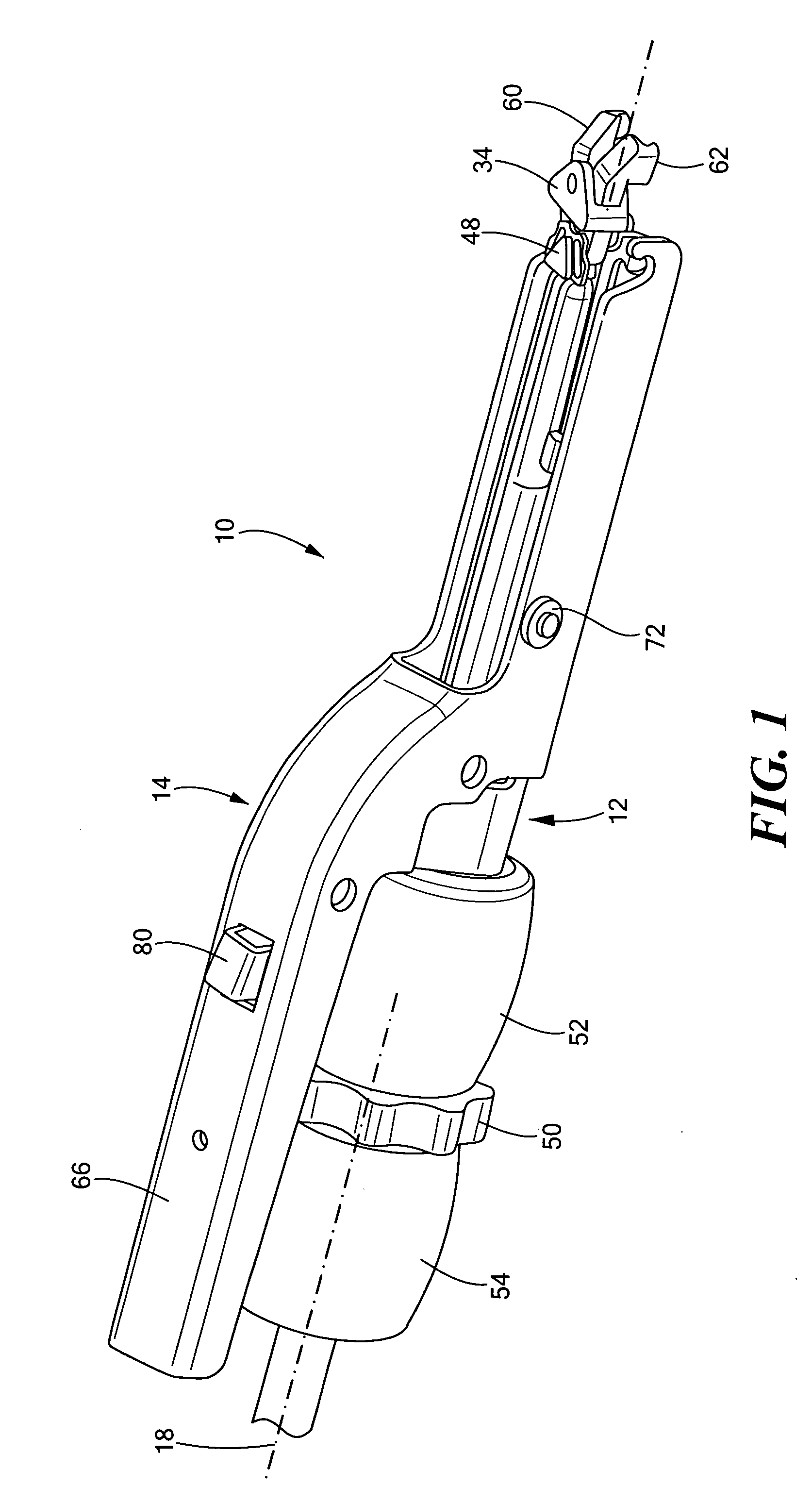
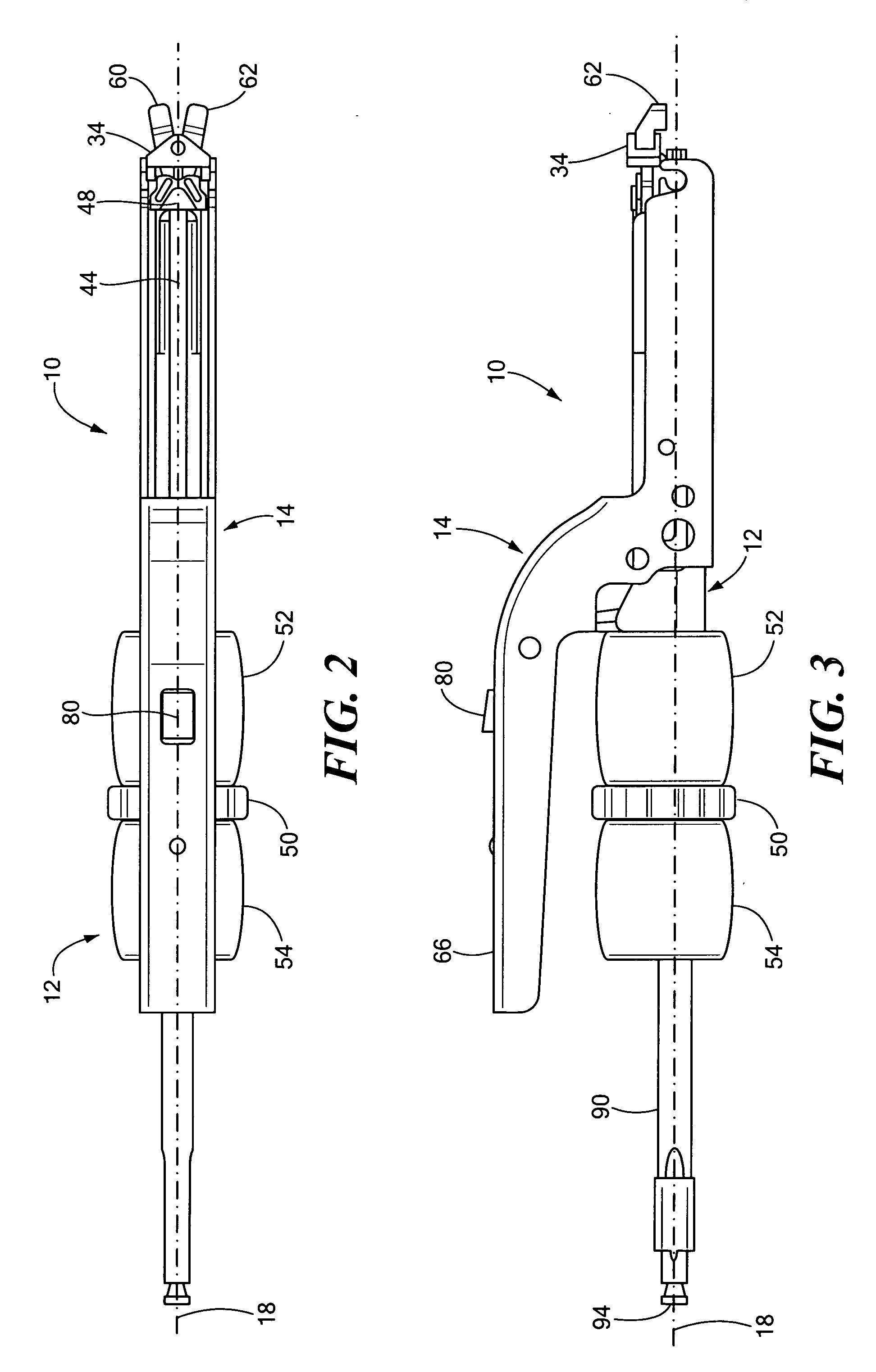
[0017] Referring now to the drawing figures in which like reference designators refer to like elements, there is shown in FIGS. 1 through 6, a medical device 10 for rod reduction during orthopedic surgery that is efficient, convenient to use and provides for simultaneous manipulation of a rod and a spinal implant along multiple axes. As shown in FIGS. 1 through 3, the medical device 10 generally includes a shaft assembly 12 and a lever assembly 14 both pivotably coupled about as well as slideably disposed on the shaft assembly 12.

[0018] As shown in FIGS. 1 through 6, the shaft assembly 12 can include a shaft 16 defining an elongate body having a longitudinal axis 18, where the shaft 16 may define a hollow channel 20 extending through the entire length of the shaft 16. The shaft 16 may further include both a proximal end 22 and a distal end 24, as well as a top portion 26 and a bottom portion 28. The shaft 16 can also define a longitudinal groove 30 on an exterior surface which exte...


PUM


Abstract

The present invention provides a medical device for reducing a rod towards a bone fastener, the medical device having a shaft defining a proximal end and a distal end, where the shaft further defines a first threaded portion. A gripper assembly may be coupled to the distal end of the shaft, where the gripper assembly is engageable with the bone fastener. The medical device also includes a slide element slideably disposed on the shaft and coupled to the gripper assembly, with the slide element defining a second threaded portion. A pusher element is slideably coupled to shaft, whereby the pusher element defines an aperture engageable with the rod. A shaft grip can be rotatably engaged with the first threaded portion of the shaft, and the shaft grip can abut at least a portion of the pusher element. The medical device can also include a jaw nut coupled to the shaft, with the jaw nut rotatably engaging the second threaded portion of the slide element, as well as a lever assembly pivotably coupled to the shaft, the lever assembly defining a rod channel engageable with the rod, and further including a latch mechanism for releasably securing the lever assembly to the shaft.

Description

CROSS-REFERENCE TO RELATED APPLICATION [0001] This application is related to and claims priority to U.S. Provisional Patent Application Ser. No. 60 / 630,467, filed Nov. 23, 2004, entitled DEFORMITY REDUCTION INSTRUMENT AND METHOD, the entirety of which is incorporated herein by reference.STATEMENT REGARDING FEDERALLY SPONSORED RESEARCH OR DEVELOPMENT [0002] n / a FIELD OF THE INVENTION [0003] The present invention relates generally to surgical instrumentation for moving one part of a surgical implant into adjacent position or contact with another surgical implant, and more particularly, to an instrument for securing a spinal rod to a bone fixation element. BACKGROUND OF THE INVENTION [0004] There are many types of spinal column disorders, including scoliosis (abnormal lateral curvature of the spine), kyphosis (abnormal forward curvature of the spine, usually in the thoracic spine), excess lordosis (abnormal backward curvature of the spine, usually in the lumbar spine), spondylolisthesi...

Claims


Application Information

Patent Timeline
IPC IPC(8): A61F2/36
CPCA61B17/7088
Inventor HAY, JAMES SCOTT
Owner MEDICAL INNOVATORS
Learn More