Retinal prosthesis

a retinal prosthesis and prosthesis technology, applied in the field of retinal prosthesis, can solve the problems of large device size, large device weight, and inability to produce adequate simulated vision to truly aid the visually impaired, and achieve the effects of high resolution display, delicate eye structure, and improved configuration

Active Publication Date: 2006-05-25
CORTIGENT INC
View PDF11 Cites 28 Cited by
  • Summary
  • Abstract
  • Description
  • Claims
  • Application Information

AI Technical Summary

Benefits of technology

[0017] The invention is a retinal prosthesis with an improved configuration mounting necessary components within and surrounding the eye. The present invention better allows for the implantation of electronics, capable of high resolution display, within the delicate eye structure. The invention further limits the necessary width of a thin film conductor passing through the sclera by use of a multiplexer external to the sclera and a demultiplexer internal to the sclera.
[0018] Applicants have discovered that a coil and electronics package around the sclera at or near 90 degrees rotation toward the lateral side of the eye has several advantages over previous designs. The secondary coil will not irritate the conjunctiva as it is placed against the sclera under the lateral rectus muscle, well behind the region where the conjunctiva attaches to the surgical limbus which is most susceptible to irritation. There is also more room between the conjunctiva and sclera on the side of the eye compared to the front of the eye. The primary coil can be placed on the temples of a pair of glasses and / or hidden by the user's hair. The spacing between primary and secondary coil can be as close, or closer, than that allowed for a coil pair located in the front of the eye or at a 45 degree angle because there are no eyelids or eyelashes to interfere with the coil.
[0019] Such a side coil design, coil and electronics outside the eye and demultiplexer inside the eye, facilitates the necessary space and heat dissipation needed for a high resolution video prosthesis.

Problems solved by technology

While some of these early attempts met with some limited success, these early prosthetic devices were large, bulky and could not produce adequate simulated vision to truly aid the visually impaired.
The device can not be powered by wires as any connection through the skin will create the risk of infection.
Battery power is not practical as batteries are bulky and surgery is required to replace them.
Implanting within the lens capsule is difficult surgery and only allows for a small diameter coil.
Implanting around the sclera under the conjunctiva and near the surgical limbus (that is at the front of the eye) allows for a larger coil but may cause irritation or damage to the conjunctiva if the coil is placed in front near the cornea.
It would be difficult or impossible to mount the electronics need for 1000 pixels within the eye.
Even if the electronics could be fit within the eye, heat dissipation would be a major issue.
It would be equally difficult to pass a cable capable of caring 1000 signal wires through the sclera.

Method used


Image

  • Retinal prosthesis
  • Retinal prosthesis
  • Retinal prosthesis

Examples


Embodiment Construction

[0027] The following description is of the best mode presently contemplated for carrying out the invention. This description is not to be taken in a limiting sense, but is made merely for the purpose of describing the general principles of the invention. The scope of the invention should be determined with reference to the claims.

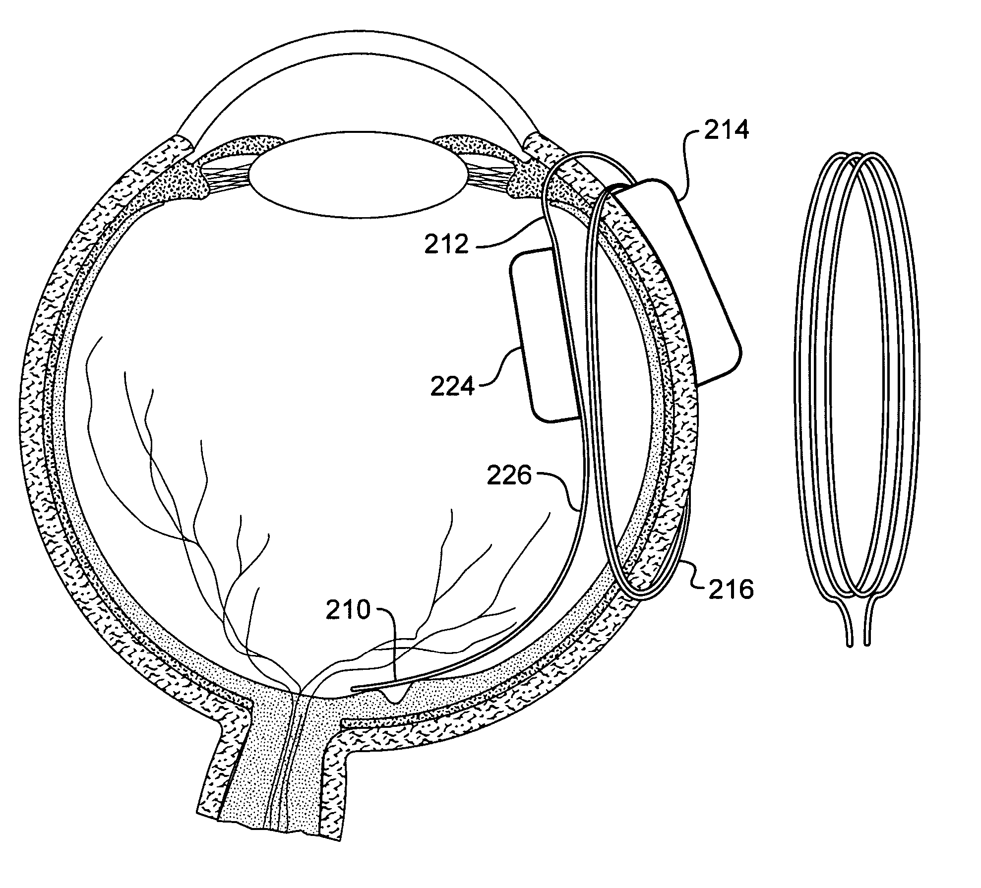
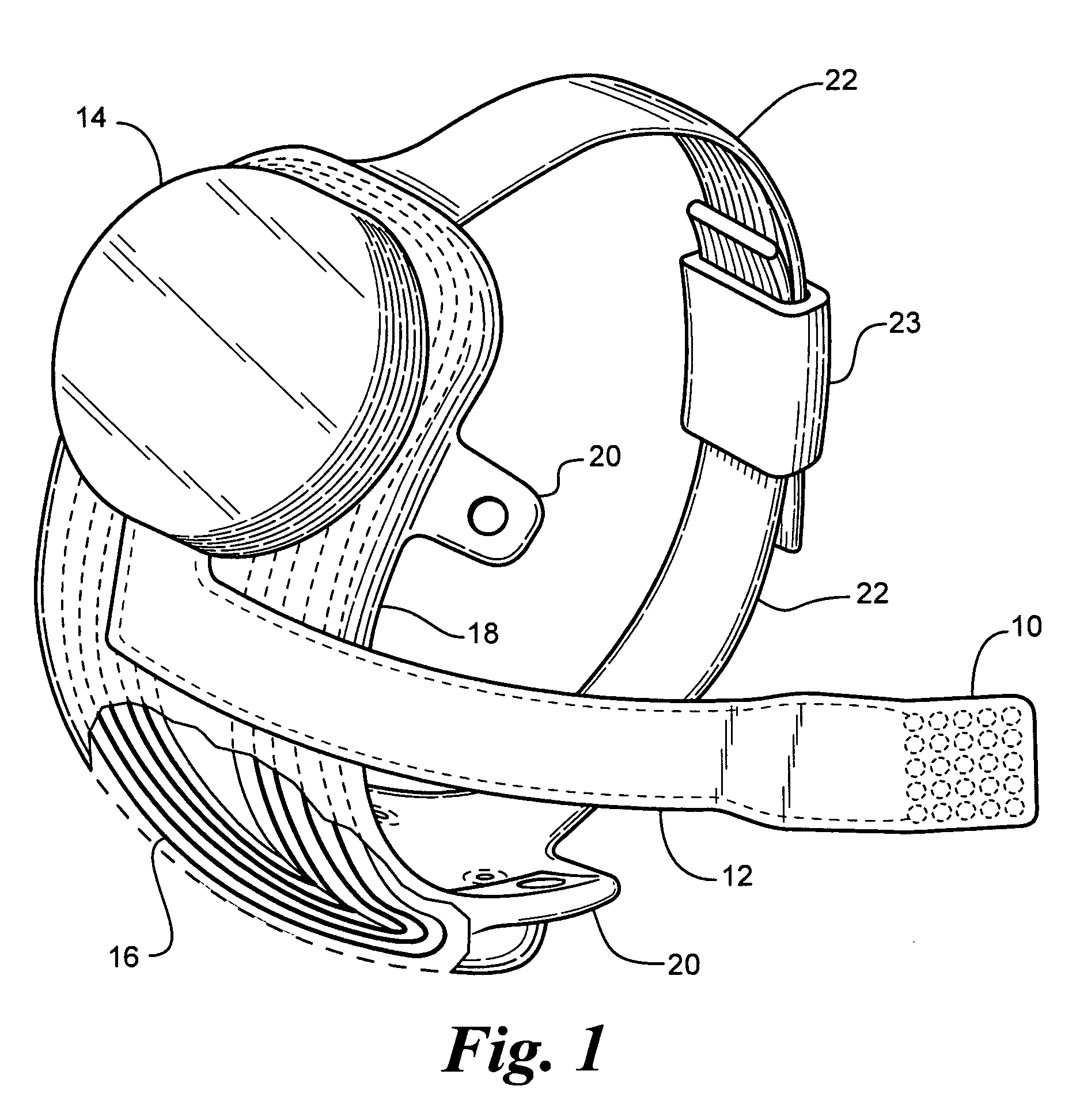
[0028]FIG. 1 shows a perspective view of the implanted portion of the preferred retinal prosthesis. An electrode array 10 is mounted by a retinal tack or similar means to the epiretinal surface. The electrode array 10 is electrically coupled by a cable 12 which pierces the sclera and is electrically coupled to an electronics package 14, external to the sclera. It is advantageous to encase the electronics within a hermetic package. This can be accomplished by use of a metal, ceramic polymer or a combination of these materials case, or by applying a thin film hermetic coating such as described in U.S. patent application 20020038134 Package for an Implantable...


PUM


Abstract

The invention is a retinal prosthesis with an improved configuration mounting necessary components within and surrounding the eye. The present invention better allows for the implantation of electronics within the delicate eye structure. The invention further limits the necessary width of a thin film conductor passing through the sclera by use of a multiplexer external to the sclera and a demultiplexer internal to the sclera.

Description

GOVERNMENT RIGHTS NOTICE [0001] This invention was made with government support under grant No. R24EY12893-01, awarded by the National Institutes of Health. The government has certain rights in the invention.FIELD OF THE INVENTION [0002] The present invention is generally directed to a visual prosthesis and more specifically to an improved mechanical and electrical configurations for retinal prosthesis for artificial vision. CROSS REFERENCE TO RELATED APPLICATIONS [0003] This application is related to, and claims priority of, provisional patent application attorney docket S300-PRO Retinal Prosthesis. BACKGROUND OF THE INVENTION [0004] In 1755 LeRoy passed the discharge of a Leyden jar through the orbit of a man who was blind from cataract and the patient saw “flames passing rapidly downwards.” Ever since, there has been a fascination with electrically elicited visual perception. The general concept of electrical stimulation of retinal cells to produce these flashes of light or phosp...

Claims


Application Information

Patent Timeline
Patent Type & Authority Applications(United States)
IPC IPC(8): A61N1/05
CPCA61N1/0543A61N1/36046
Inventor GREENBERG, ROBERTTALBOT, NEILMECH, BRIAN V.LITTLE, JAMES
Owner CORTIGENT INC
Why Eureka
Try Eureka