Electronic pet containment system with improved transmitter with constant field generation

a technology of constant field generation and electronic animal containment, which is applied in the field of electronic animal containment or confinement system, can solve problems such as damage or destruction of the transmitter circuitry

Inactive Publication Date: 2006-06-01
WOODSTREAM CORP
View PDF31 Cites 59 Cited by
  • Summary
  • Abstract
  • Description
  • Claims
  • Application Information

AI Technical Summary

Benefits of technology

[0019] It is another object of the present invention to provide an improved system for protecting a transmitter in a pet confinement system against lightning strikes.

Problems solved by technology

Should lightening strike at or near the wire, the transmitter circuitry may be damaged or destroyed.

Method used


Image

  • Electronic pet containment system with improved transmitter with constant field generation
  • Electronic pet containment system with improved transmitter with constant field generation
  • Electronic pet containment system with improved transmitter with constant field generation

Examples


Embodiment Construction

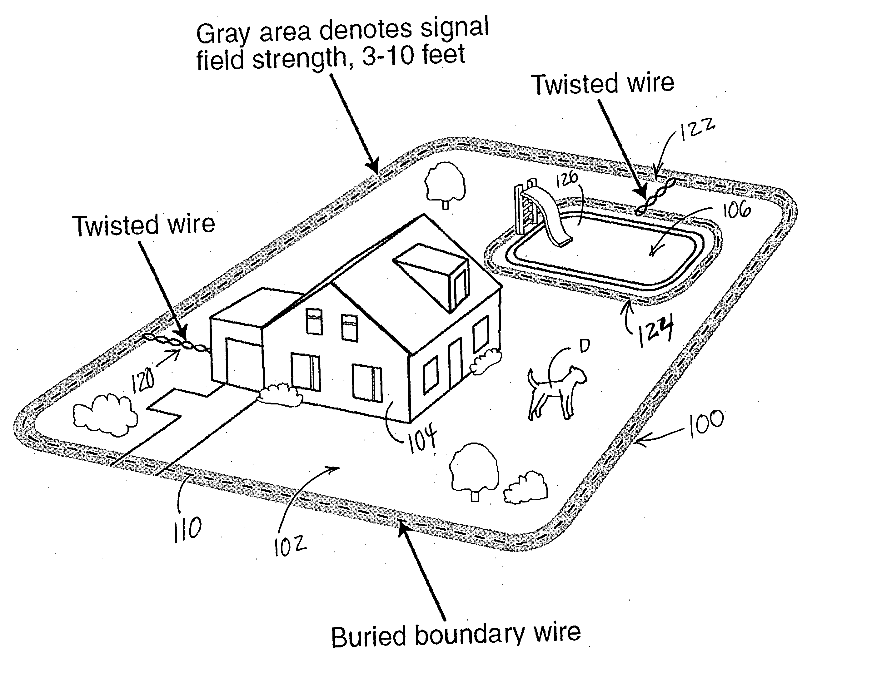
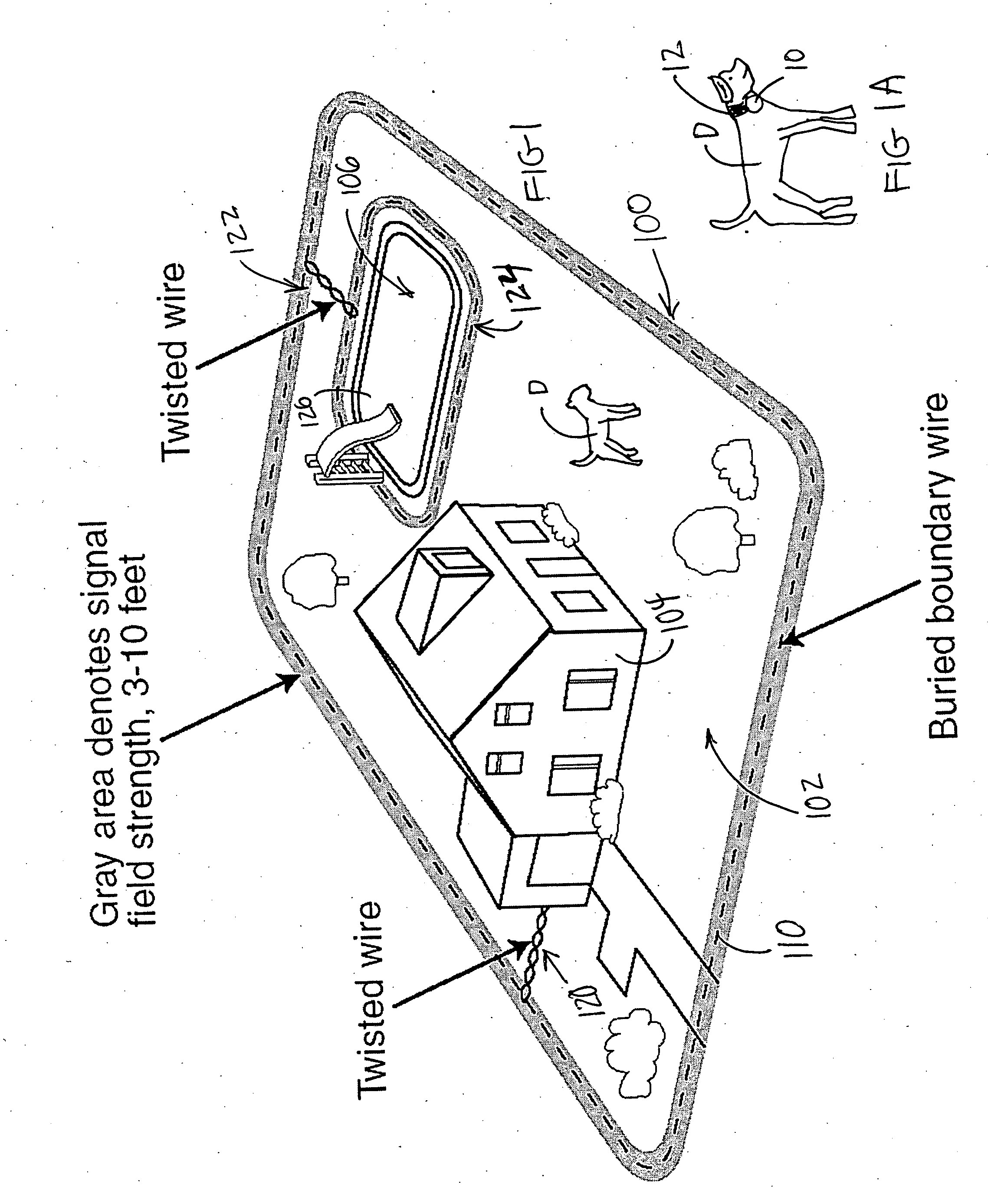
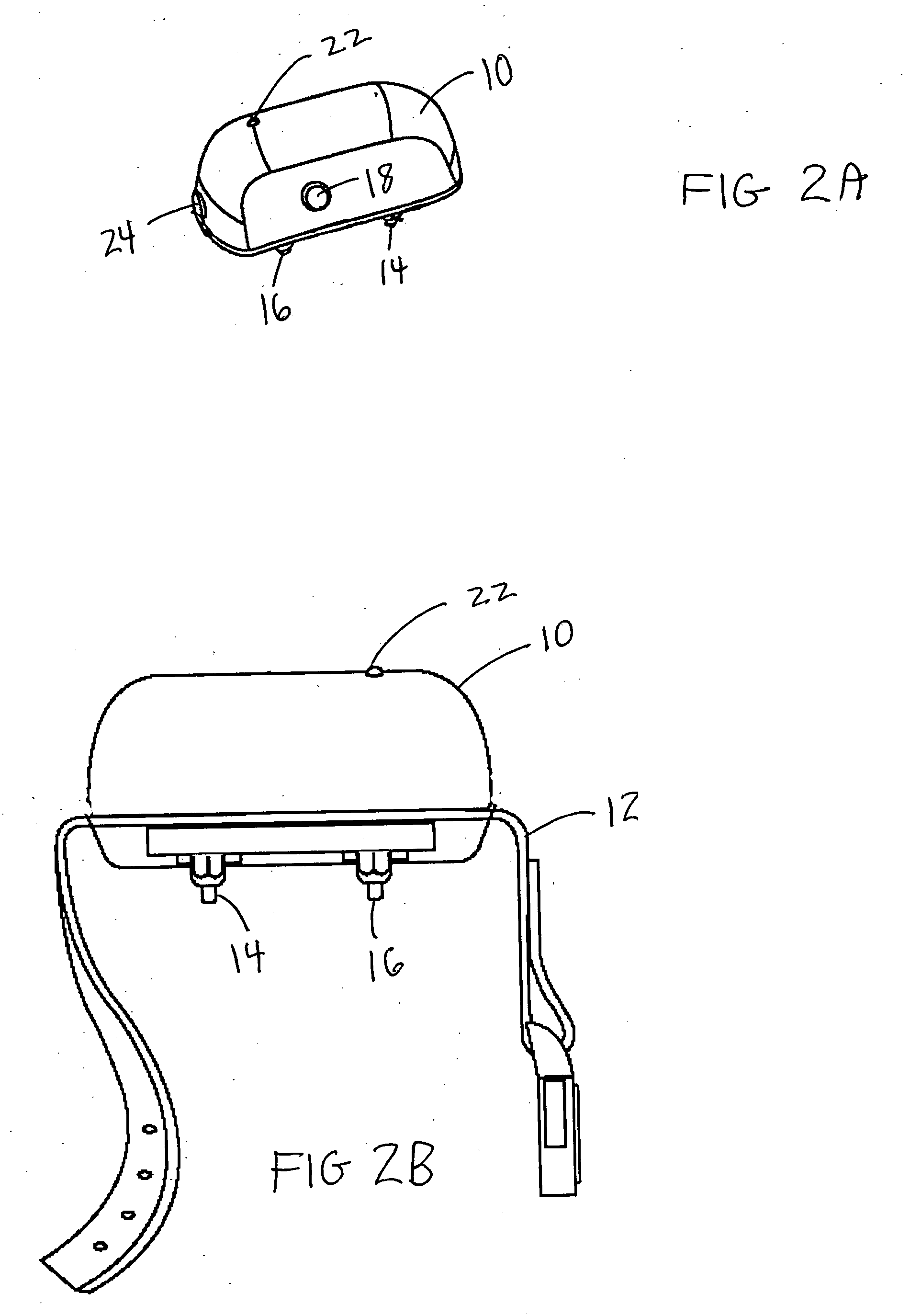
[0029] With reference to FIGS. 1 through 3, the basic elements of the inventive pet confinement system are shown. FIGS. 1A, 2A, 2B and 3 generally show a receiver 10 that is secured to a collar 12 that is worn by a dog D around its neck. The receiver contains two probes 14 and 16 that make contact with the skin of the dog so that when the dog gets too close to an electrified boundary, a shock is created within the receiver 10 and passed through the probes 14 and 16 into the dog as way to alert the dog that behavior such as approaching the fence should not be done. The receiver 10 also contains a charger receptacle 18 that mates with a complementary connection provided in the transmitter 20, which is the subject of this invention. The receiver 10 contains a light emitting diode (LED) 22 which indicates when the receiver is functioning and an on / off switch 24 for placing the receiver in an on position and in a desired mode of operation. One such receiver that is contemplated to be use...


PUM


Abstract

An electronic animal containment or confinement system that contains a transmitter which generates a regulated signal through a boundary antenna made from a buried wire. The regulated signal creates a field signal of a predetermined width regardless of the length of the wire used to define the boundary antenna. The field signal is received by a receiver worn by a dog. If the dog gets too close to the field signal, the receiver generates a current that passes across a pair of probes that contact the skin of the dog in order to give the dog a shock. This represents a form of training to teach the dog to respect an electrified boundary formed by the buried wire. There is also provided a system for protecting a transmitter in a pet confinement system against lightning strikes.

Description

BACKGROUND OF THE INVENTION [0001] 1. Field of the Invention [0002] The present invention relates to an electronic animal containment or confinement system and, more specifically to a pet confinement system that contains a transmitter which generates a regulated signal through a boundary antenna made from a buried wire. The regulated signal creates a field signal of a predetermined width regardless of the length of the wire used to define the boundary antenna. [0003] 2. Description of Prior Art [0004] Over the years, electronic animal containment systems have become very popular because they use electronic signals traveling though a buried wire to create a boundary defining a predetermined area within a property. In this way, the property owner does not have to erect a fence in order to ensure that an animal is confined within a desired space. [0005] In a typical electronic animal confinement system, a boundary signal emitter wire in the form of a boundary antenna is buried along th...

Claims


Application Information

Patent Timeline
Patent Type & Authority Applications(United States)
IPC IPC(8): A01K15/04
CPCA01K15/023
Inventor GOMEZ, DAVID ROGERS
Owner WOODSTREAM CORP
Why Eureka
Try Eureka