Dispenser with lock

a technology of dispenser and lock, which is applied in the direction of packaging, liquid transfer device, single-unit apparatus, etc., can solve the problems of actuator unprotected, actuator could be inadvertently bumped and perhaps partially depressed or actuated, possibly lost or inadvertently discarded, etc., and achieve the effect of increasing resistan

Inactive Publication Date: 2006-06-01
SEAQUIST PERFECT DISPENSING FOREIGN INC
View PDF99 Cites 41 Cited by
  • Summary
  • Abstract
  • Description
  • Claims
  • Application Information

AI Technical Summary

Benefits of technology

[0021] A locking sleeve is rotatably mounted around both the stem and the actuator. The locking sleeve defines at least a first upper abutment edge for engaging an underside of the actuator lateral projection (which may be the dispensing nozzle in the preferred embodiment) to prevent downward movement of the actuator when the locking sleeve is in a first rotated position to lock the dispensing assembly from being actuated. The locking sleeve also defines at least a first recess for accommodating downward movement of the actuator lateral projection (which may be the nozzle or spout in the preferred embodiment) when the locking sleeve is in a second rotated position while the actuator is depressed to actuate the dispensing assembly.
[0022] In a presently most preferred form of the dispensing assembly of the present invention, the assembly includes a trigger mechanism for moving the actuator. A trigger is pivotally mounted to a trigger support that is carried by the assembly. The trigger extends over a portion of the actuator and defines an aperture in front of the actuator to accommodate dispensing of the fluent material from the actuator through the aperture. The trigger engages the top of the actuator and has a finger-grippable lever portion extending from the trigger aperture below the elevation of the aperture. In the preferred embodiment, the trigger provides the user with some mechanical advantage to move the actuator downwardly to actuate the dispensing assembly. The preferred form of the trigger also prevents removal of the actuator.
[0023] In the preferred form of the dispensing assembly of the present invention, the locking mechanism is easily operable by rotation, such as through a 90 degree increment between the locked and unlocked conditions.
[0024] Further, in the most preferred form of the invention, the locking mechanism provides a tactile sensation of relieved resistance when the locking mechanism is rotated to the unlocked or locked positions.
[0026] In the preferred embodiment, the locking mechanism will also provide a tactile sensation of increased resistance when the user attempts to rotate the locking mechanism away from the locked or unlocked positions.

Problems solved by technology

However, even a hood can be knocked off of the package, and that would leave the actuator unprotected such that the actuator could be inadvertently bumped and perhaps partially depressed or actuated.
In those designs where a hood is employed, the disadvantages are that such a hood is an additional component that must be provided by the manufacturer, and the hood must subsequently be removed from the pump by the user (and perhaps retained by the user for subsequent replacement on the pump).
When the clip is removed, it could possibly be lost or inadvertently discarded.
Such a removable locking plug also could be lost or inadvertently discarded, or even purposely stolen.

Method used


Image

  • Dispenser with lock
  • Dispenser with lock
  • Dispenser with lock

Examples


Embodiment Construction

[0057] While this invention is susceptible of embodiment in many different forms, this specification and the accompanying drawings disclose only some specific forms as examples of the invention. The invention is not intended to be limited to the embodiments so described, however. The scope of the invention is pointed out in the appended claims.

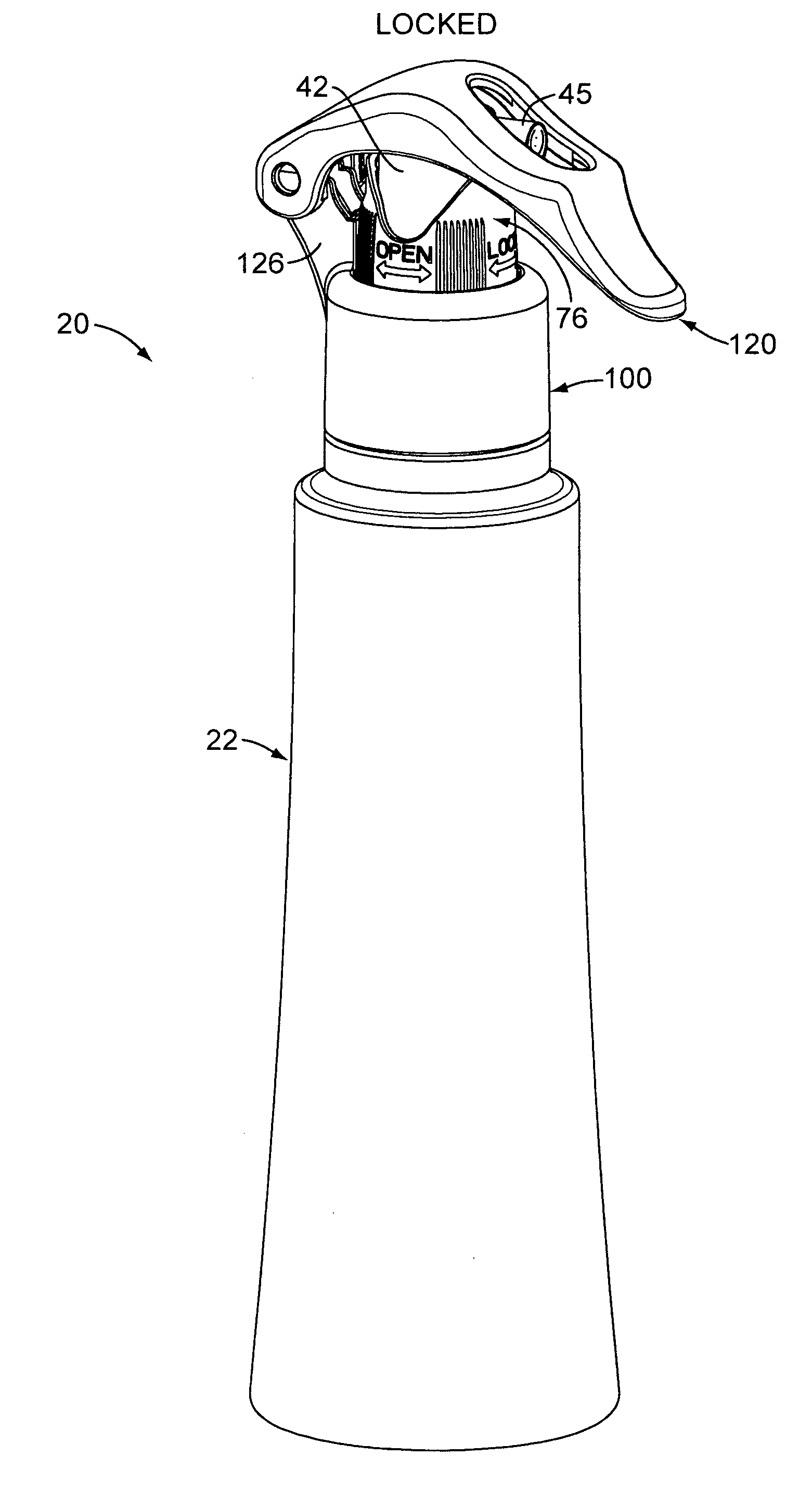
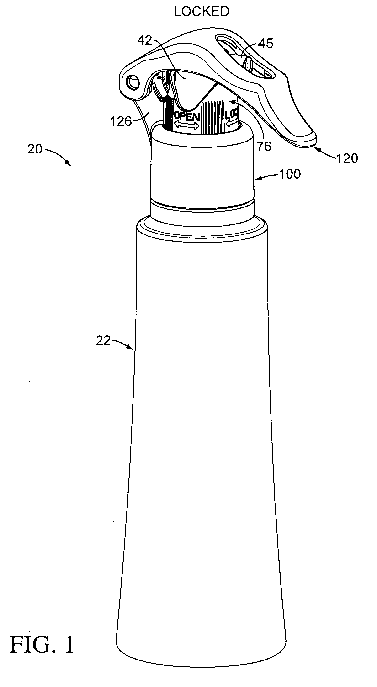
[0058] For ease of description, the components of this invention and the container employed with the components of this invention are described in the normal (upright) operating position, and terms such as upper, lower, horizontal, etc., are used with reference to this position. It will be understood, however, that the components embodying this invention may be manufactured, stored, transported, used, and sold in an orientation other than the position described.

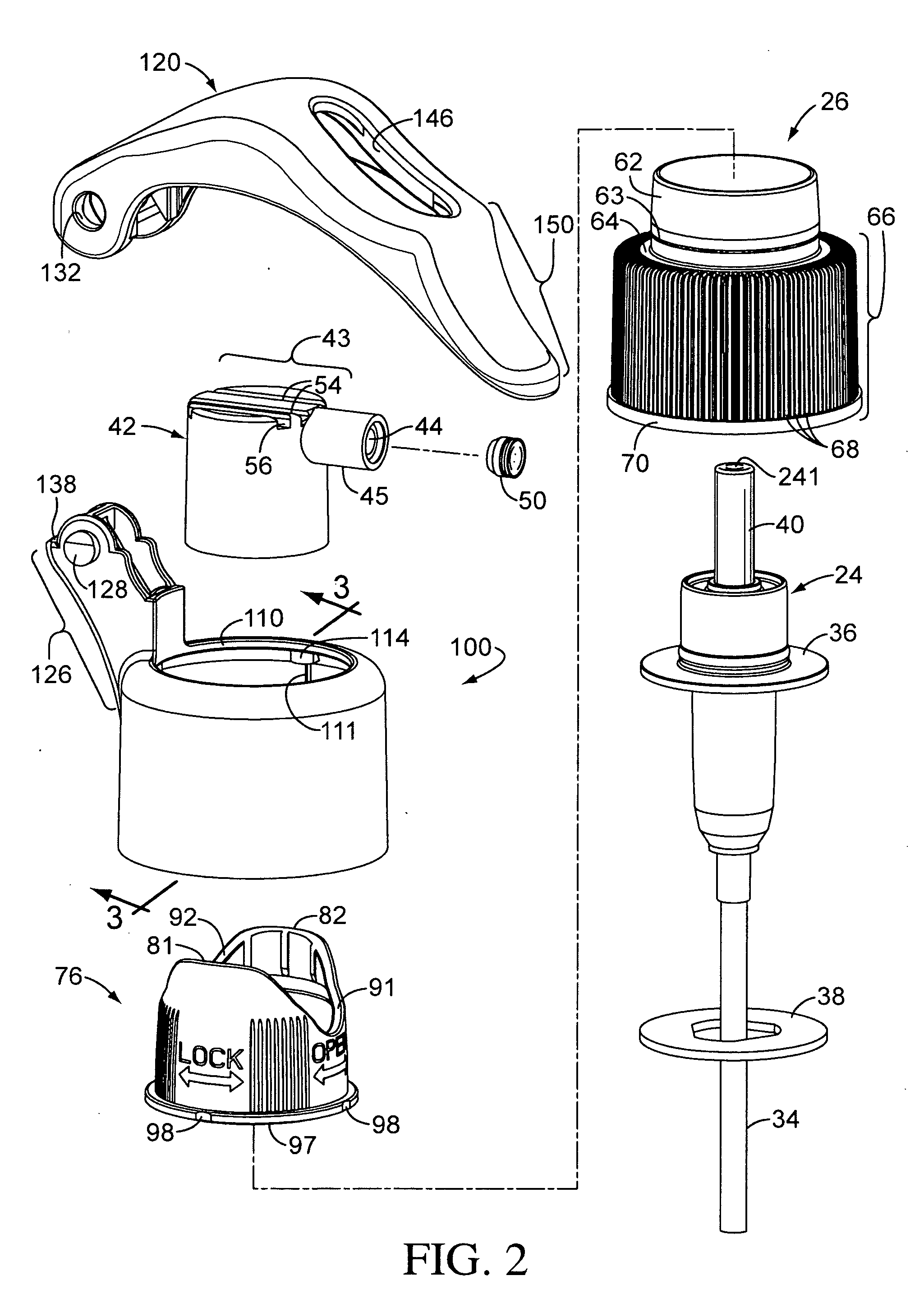
[0059] Figures illustrating the components of this invention and the container show some conventional mechanical elements that are known and that will be recognized by one skilled in ...


PUM


Abstract

A dispensing assembly is provided for a container of fluent material. A hand-operable dispenser cartridge is adapted to be mounted to the container. An actuator with a lateral projection, which may be a nozzle or spout, is mounted on the cartridge. A locking sleeve is mounted around the cartridge and has an upper abutment edge and a recess. The locking sleeve can be rotated between a first rotated position preventing actuation of the dispenser and a second rotated position permitting actuation of the dispenser.

Description

CROSS REFERENCE TO RELATED APPLICATION [0001] This application is a continuation-in-part of the U.S. design patent application Serial No. 29 / 218,428, filed Nov. 29, 2004.TECHNICAL FIELD [0002] The present invention relates generally to a hand-operable dispensing package for fluent material, typically as a spray. The invention more particularly relates to an assembly of components for mounting a dispenser to a container in a way that can selectively permit or prevent actuation of the dispenser. The invention can be incorporated in a system employing either an aerosol dispensing valve or dispensing pump. BACKGROUND OF THE INVENTION AND TECHNICAL PROBLEMS POSED BY THE PRIOR ART [0003] Hand-operable or finger-operable dispensers (including, for example, both dispensing pumps and aerosol dispensing valves) are typically adapted to be mounted on hand-held containers that are commonly used for liquid products. Typically, some pumps and valves operate with a suitable discharge structure, su...

Claims


Application Information

Patent Timeline
Patent Type & Authority Applications(United States)
IPC IPC(8): B67D5/40B67D7/58
CPCB05B11/3014B05B11/3057B05B11/3059B65D83/201B65D83/22B05B11/1014B05B11/1059B05B11/1057
Inventor WALTERS, PETER J.KSIAZK, JASON A.CHO, SEAN H.HALLMAN, PAUL E.WERNER, JONATHAN D.BRAUN, CRAIG
Owner SEAQUIST PERFECT DISPENSING FOREIGN INC
Why Eureka
Try Eureka