
Damping valve and shock absorber using same

Active Publication Date: 2006-06-01
KYB CORP
View PDF9 Cites 71 Cited by
  • Summary
  • Abstract
  • Description
  • Claims
  • Application Information

AI Technical Summary

Benefits of technology

[0006] However, because of the use of a damping valve through which hydraulic fluid flows in a one-way direction, the shock absorber needs to have four check valves provided in the entire shock absorber including the circuit, leading to high costs and complicated structure.
[0007] In this connection, a possible idea for making the structure of a shock absorber simple is of providing two damping valves through which hydraulic fluid passes in a one-way direction.
[0008] However, when control on the damping force of the shock absorber is required, the flow rate of the hydraulic fluid passing through the damping valve is adjusted. For this reason, each of the damping valves needs to be equipped with a solenoid, resulting in high costs.
[0009] Accordingly, the present invention has been made to improve the above problems. An object of the present invention is to provide a damping valve capable of reducing the manufacturing cost for a shock absorber. Another object of the present invention is to provide a shock absorber capable of being manufactured at low costs.

Problems solved by technology

However, because of the use of a damping valve through which hydraulic fluid flows in a one-way direction, the shock absorber needs to have four check valves provided in the entire shock absorber including the circuit, leading to high costs and complicated structure.
For this reason, each of the damping valves needs to be equipped with a solenoid, resulting in high costs.

Method used


Image

  • Damping valve and shock absorber using same
  • Damping valve and shock absorber using same
  • Damping valve and shock absorber using same

Examples


Embodiment Construction

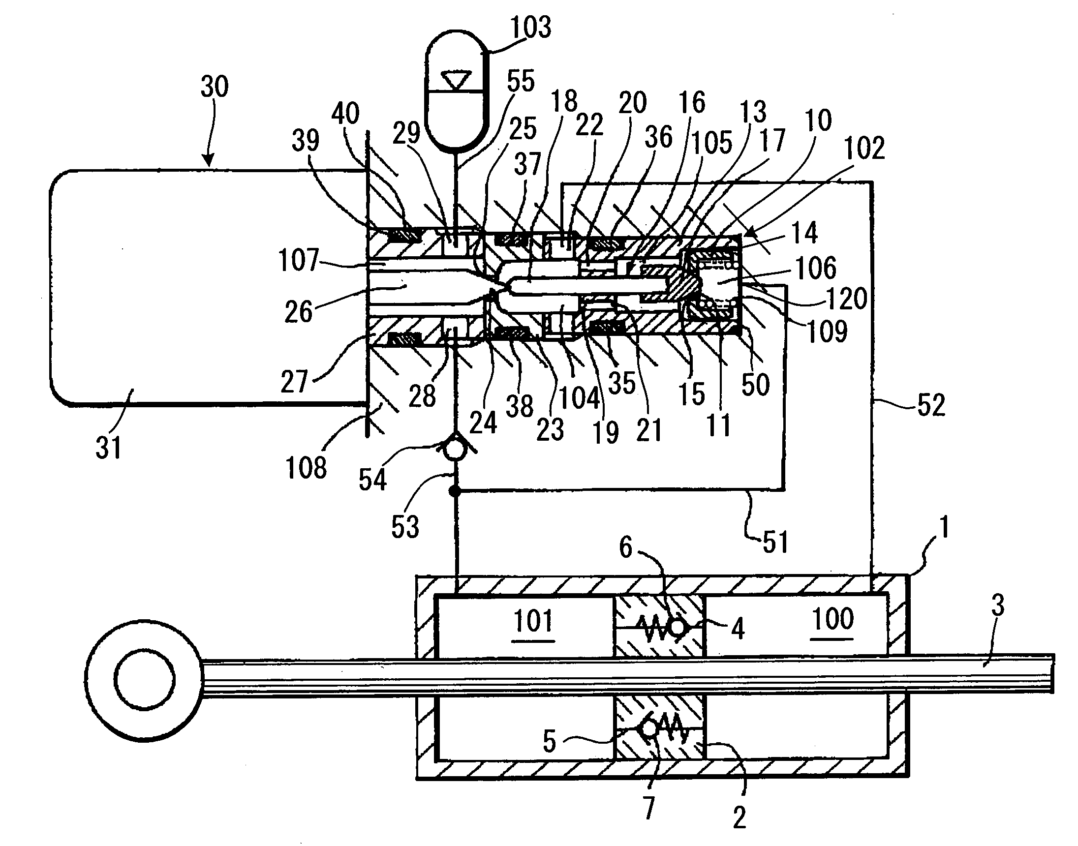
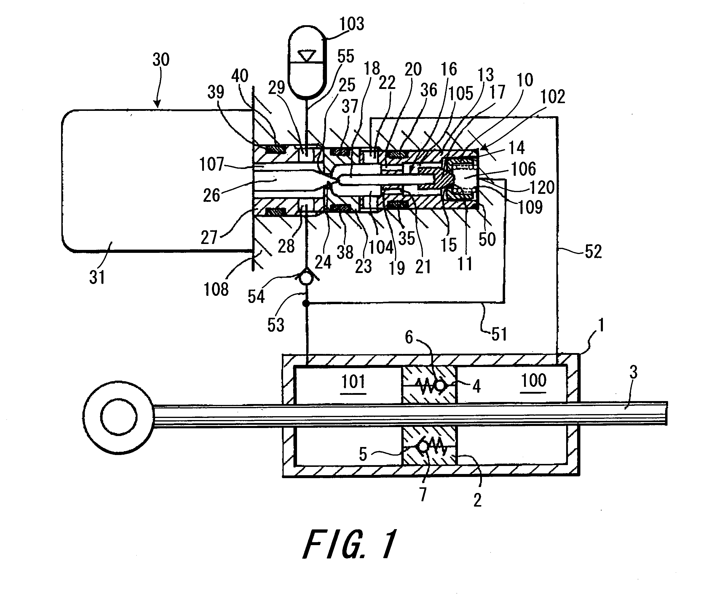
[0018] The present invention will be described below with reference to the accompanying drawings. FIG. 1 is a circuit diagram with a vertically sectional view illustrating a shock absorber in an embodiment.

[0019] As illustrated in FIG. 1, the shock absorber in the embodiment of the present invention includes a cylinder 1, a piston 2 serving as a defining member for dividing the inside of the cylinder 1 into two pressure chambers 100 and 101, a valve 102, and an accumulator 103 serving as a reservoir.

[0020] The piston 2 is slidably inserted in the cylinder 1 and the piston 2 defines the pressure chambers 100 and 101 therein. The pressure chambers 100 and 101 are filled with liquid such as hydraulic oil.

[0021] The piston 2 is connected to a piston rod 3. The shock absorber is structured as a so-called double rod type and has the piston rod 3, extending through shaft central portions of two ends of the cylinder 1.

[0022] Passages 4 and 5 are provided in the piston 2, so that the two...


PUM


Abstract

A damping valve (102) comprises: a first valve element (16); a first valve seat (15) in which the first valve element (16) is seated; a second valve element (26) placed in series with the first valve element (16); a second valve seat (25), placed between the first and second valve elements (16) and (26), in which the second valve element (26) is seated; an biasing mechanism (30) for biasing the second valve element (26) toward the second valve seat (25) and biasing the first valve element (16) toward the first valve seat (15) via the second valve element (26); a first liquid chamber (106); a second liquid chamber (104); and a third liquid chamber (107).

Description

FIELD OF THE INVENTION [0001] This invention relates to a damping valve and a shock absorber. BACKGROUND OF THE INVENTION [0002] A shock absorber is mounted on a vehicle or the like for the purpose of damping vibrations generated in a vehicle body or a vehicle steering, for example. [0003] In particular, when shock absorbers are used for the purpose of damping vibrations generated in a steering of a two-wheel vehicle, the shock absorbers desirably generate an equal damping force at each of the right and left sides against the swing of the steering in the lateral direction with respect to the neutral position of the shock absorbers. [0004] JP2004-231036A published by Japanese Patent Office in 2004 discloses a shock absorber which has a circuit designed to use a single damping valve and allow hydraulic fluid filling the shock absorber to always pass through the damping valve in a one-way direction when flowing in and out of two pressure chambers in the shock absorbers. [0005] More spe...

Claims


Application Information

Patent Timeline
IPC IPC(8): F16F9/50
CPCF16F9/464
Inventor HANAWA, NOBUMICHI
Owner KYB CORP
Learn More