Method for Electro-Chemical Processing of a Work Piece and Electrode for Such a Method

a work piece and electrochemical processing technology, applied in the direction of machining electrodes, electrical equipment, electric-based machining apparatus, etc., can solve the problems of electrode wear and tear, small and complex work piece surfaces that are not producible or only in a relatively cost-effective manner, electrodes are subjected to material wear and tear, etc., to increase the flushing effect, and increase the effect of material removal precision

Inactive Publication Date: 2007-11-08
FRUTH CARL JOHANNES
View PDF6 Cites 25 Cited by
  • Summary
  • Abstract
  • Description
  • Claims
  • Application Information

AI Technical Summary

Benefits of technology

[0028] A further exemplary embodiment of the present inventive method provides that the application of ultrasound is superimposed during the metal ion removal in order to, e.g., increase the flushing effect.
[0029] A further exemplary embodiment of the present invention provides that processing takes place with vibrations in various effective directions again in order to increase the flushing effect or to increase the precision of the material removal from the work piece. In this way, complex, specific shapes, such as screw threads, under-cuts, inner threads or gear geometries could be produced.

Problems solved by technology

A problem of these material removal methods is that small and complex work piece surfaces are not producible or only in a relatively cost-ineffective manner.
Other materials are only suitable therefor with severe restrictions.
However, in electrical discharge erosion, it is disadvantageous that the electrodes are subjected to material wear and tear and the processing of a work piece takes a long time and is thus expensive.
Moreover, deep slots or similar geometries in work pieces are hardly possible with the previous electrodes for electrolyte machining, because the necessary flushing ducts can not be generated or only with substantial effort.
This leads to an oscillating electrode movement.

Method used


Image

  • Method for Electro-Chemical Processing of a Work Piece and Electrode for Such a Method
  • Method for Electro-Chemical Processing of a Work Piece and Electrode for Such a Method
  • Method for Electro-Chemical Processing of a Work Piece and Electrode for Such a Method

Examples


Embodiment Construction

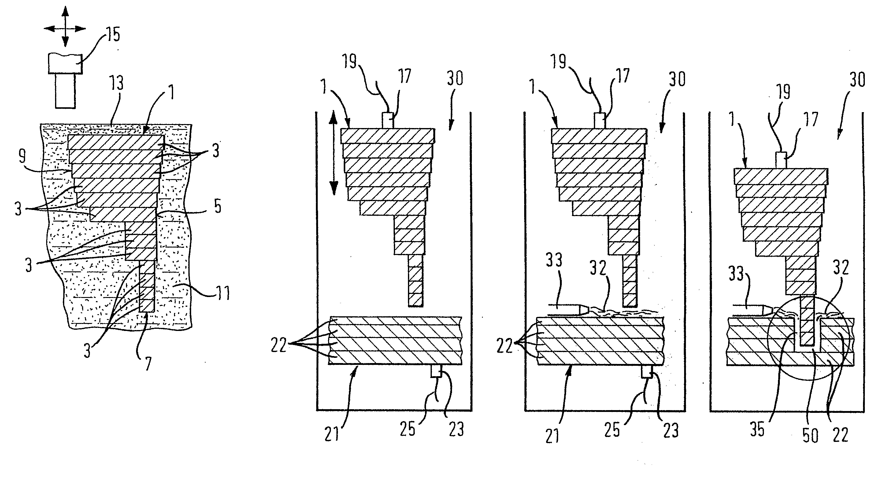
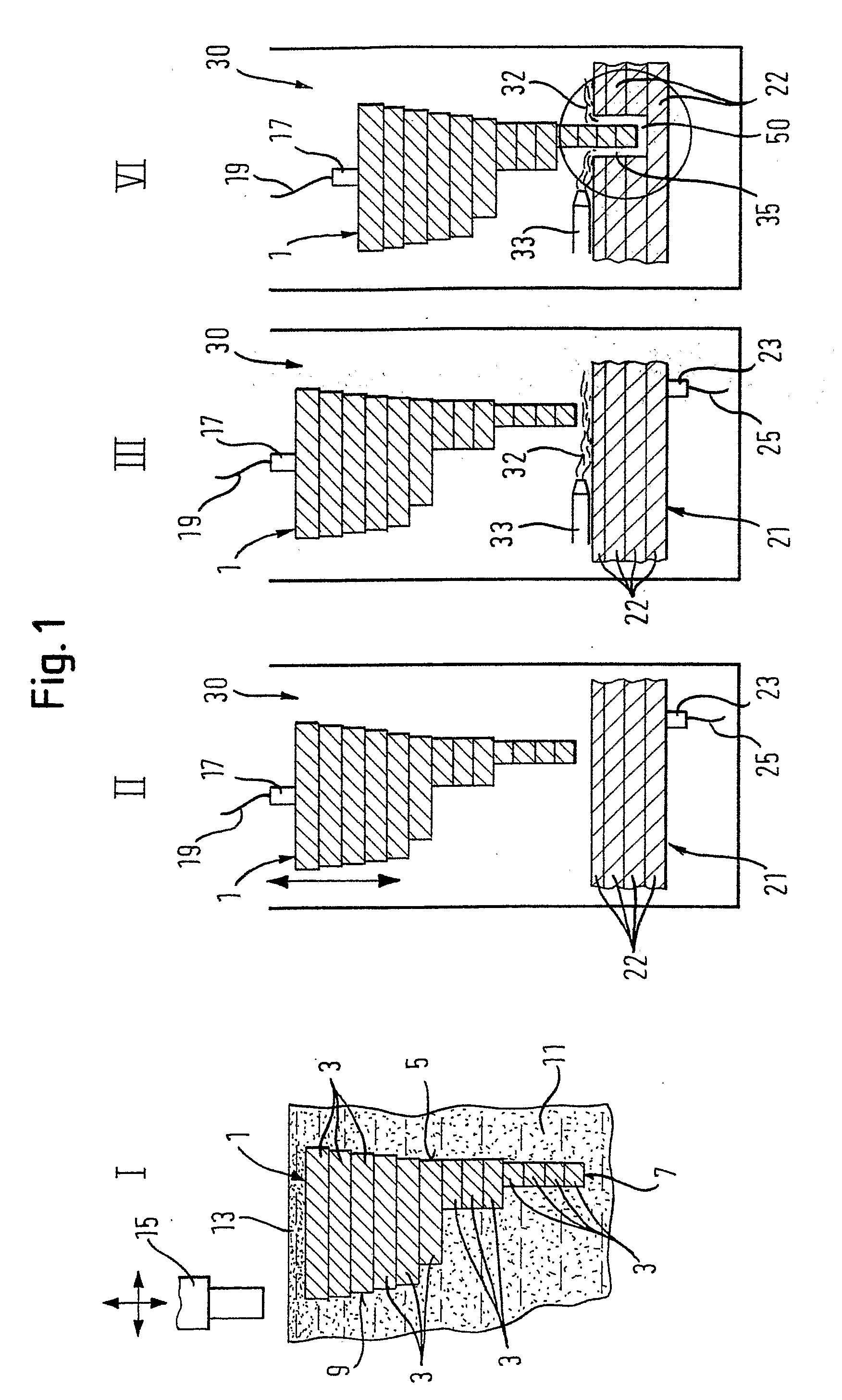
[0053] A first exemplary embodiment of the present invention is explained in more detail in the following with reference to FIG. 1. The stereo-lithography process utilized herein is purely exemplary and can be replaced by other above-mentioned layered-construction processes.

[0054] As is shown in partial step I of FIG. 1, an electrode body 1 is constructed in layers in a known manner in a RP-machine (rapid prototyping) in a liquid synthetic material bath 11. For this purpose, the desired cross section of layer 3 of electrode body 1 is fabricated using a laser 15 that is, in the view illustrated in FIG. 1, movable in the horizontal plane and is also height-adjustable. The laser 15 is moved in the horizontal plane according to the desired contour and a part of the synthetic material layer 13 of the liquid synthetic material 11 is exposed with appropriate illumination and is thus cured. Consequently, arbitrary contours and layer shapes 3 can be fabricated.

[0055] As soon as the desired...


PUM

PropertyMeasurementUnit
conductiveaaaaaaaaaa
voltageaaaaaaaaaa
metallicaaaaaaaaaa

Abstract

The invention concerns a method for processing a work piece (21), in which a work piece (21) is constructed in layers (3) from a conductive material using a rapid prototyping process. The work piece (21) constructed in layers (3) is contacted in an anodic manner. Then, a tool (1) is disposed opposite to a to-be-processed site of the work piece (21) such that a gap (50) remains therebetween. The tool (1) is contacted in a cathodic manner and a conductive medium (32) is brought into the gap (50) so that current flows by applying an electronic voltage and metal ions are dissolved from the work piece (21) by electrolysis, whereby a defined removal of material from the work piece (21) takes place. The invention further concerns a method for producing a tool to be utilized as an electrode (1) in an ECM method and an electrode (1) for usage in an ECM method for electro-chemical processing of a work piece (21).

Description

TECHNICAL FIELD [0001] The present invention concerns various methods for electro-chemical processing of a work piece. Further, the invention concerns methods for manufacturing a tool to be used as an electrode in an electro-chemical processing method, which tool is designed for electro-chemical processing of a work piece. Moreover, the invention concerns electrodes that are designed for usage in a method for electro-chemical processing of a work piece. BACKGROUND OF THE INVENTION [0002] For processing work pieces and in particular for manufacturing specified work piece surfaces, material removing methods, such as milling and lathing, are generally known. A problem of these material removal methods is that small and complex work piece surfaces are not producible or only in a relatively cost-ineffective manner. [0003] In addition, for special applications, the removal of material using electrical discharge erosion, electrolytic machining and by metal etching is known. These three met...

Claims


Application Information

Patent Timeline
Patent Type & Authority Applications(United States)
IPC IPC(8): B23H3/00
CPCB23H3/00B23H3/04B29C67/0051B23H9/00B23H3/06B33Y80/00
Inventor FRUTH, CARL JOHANNES
Owner FRUTH CARL JOHANNES
Why Eureka
Try Eureka