Al technical title is built by PatSnap Al team. It summarizes the technical point description of the patent document.
a technology for hand-held controllers and vehicles, applied in the direction of instruments, coding, pulse techniques, etc., can solve the problems of operators being thrown around the vehicle's cockpit, increasing complexity of control panels, and serious injuries
Active Publication Date: 2006-06-01
MEASUREMENT SYST
View PDF11 Cites 84 Cited by
Summary
Abstract
Description
Claims
Application Information
AI Technical Summary
This helps you quickly interpret patents by identifying the three key elements:
Problems solved by technology
Method used
Benefits of technology
[0007] In one aspect of the invention, there is provided a handheld controller for use by a human operator in controlling a plurality of aspects of a vehicle's operation. The handheld controller comprises a box portion, handle portions extending from the box portion, a first plurality of devices disposed on a top surface of the box portion, and a second plurality of devices disposed on a bottom surface of the box portion. The human operator grasps the handle portions, the first plurality of devices are manipulated by the human operator's thumbs, the second plurality of devices are manipulated by the human operator's fore fingers, and the handheld controller provides a control signal to the vehicle in response to manipulation of any of the first and second plurality of devices. In various embodiments, the control signal may be provided via a cable or by a wireless signal. The handheld controller and the human operator may be remote from the vehicle or located in the vehicle.
[0008] In another aspe
Problems solved by technology
While this served well in past, the increasing number of features found in modern vehicles leads to an increasingly complex control panel, while at the same time requiring the operator to perform control tasks at a faster rate.
Moreover, another drawback of the modern
Method used
Image
Click on the blue label to locate the original text in one second.
Reading with bidirectional positioning of images and text.
Examples
Embodiment Construction
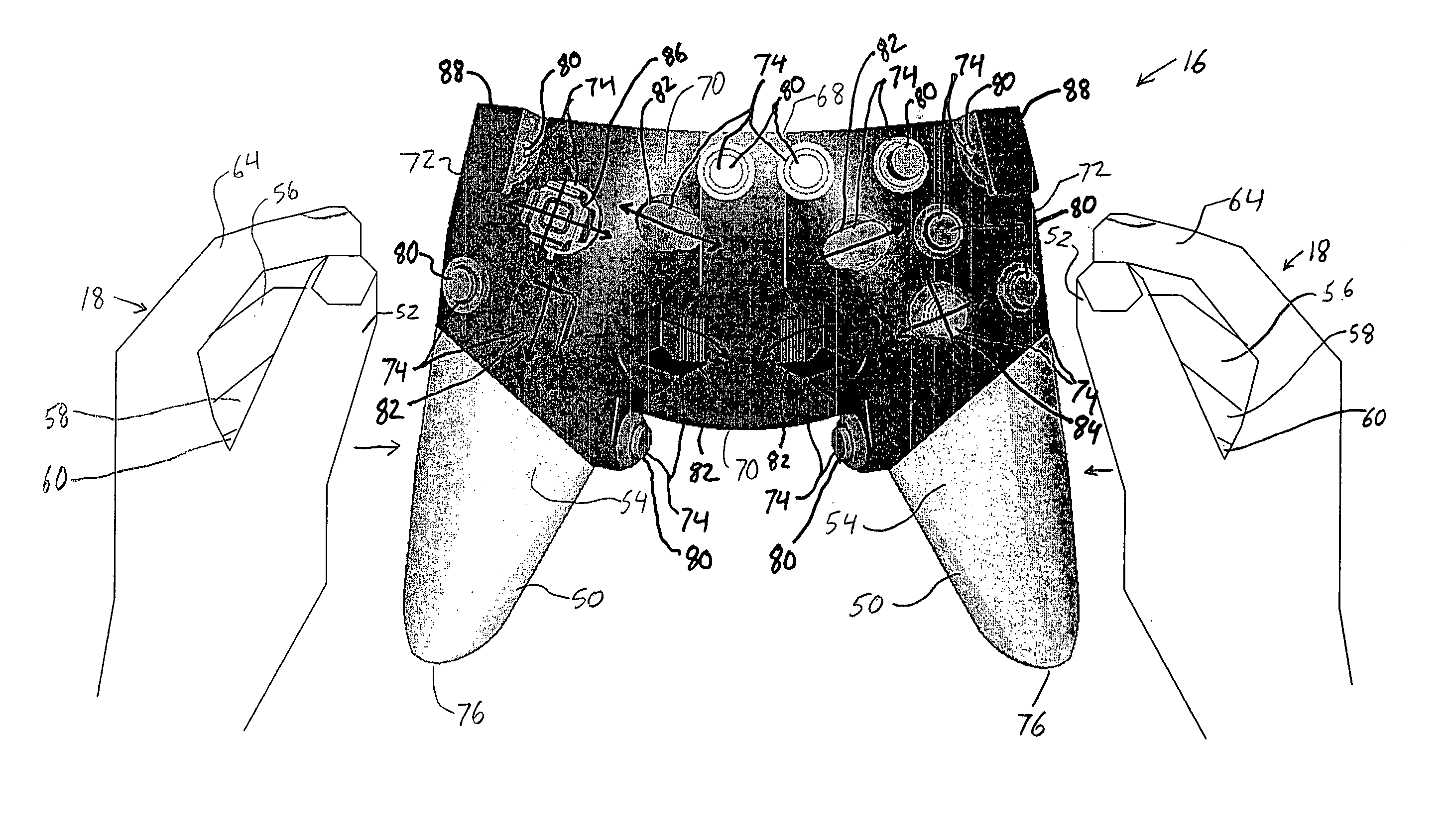
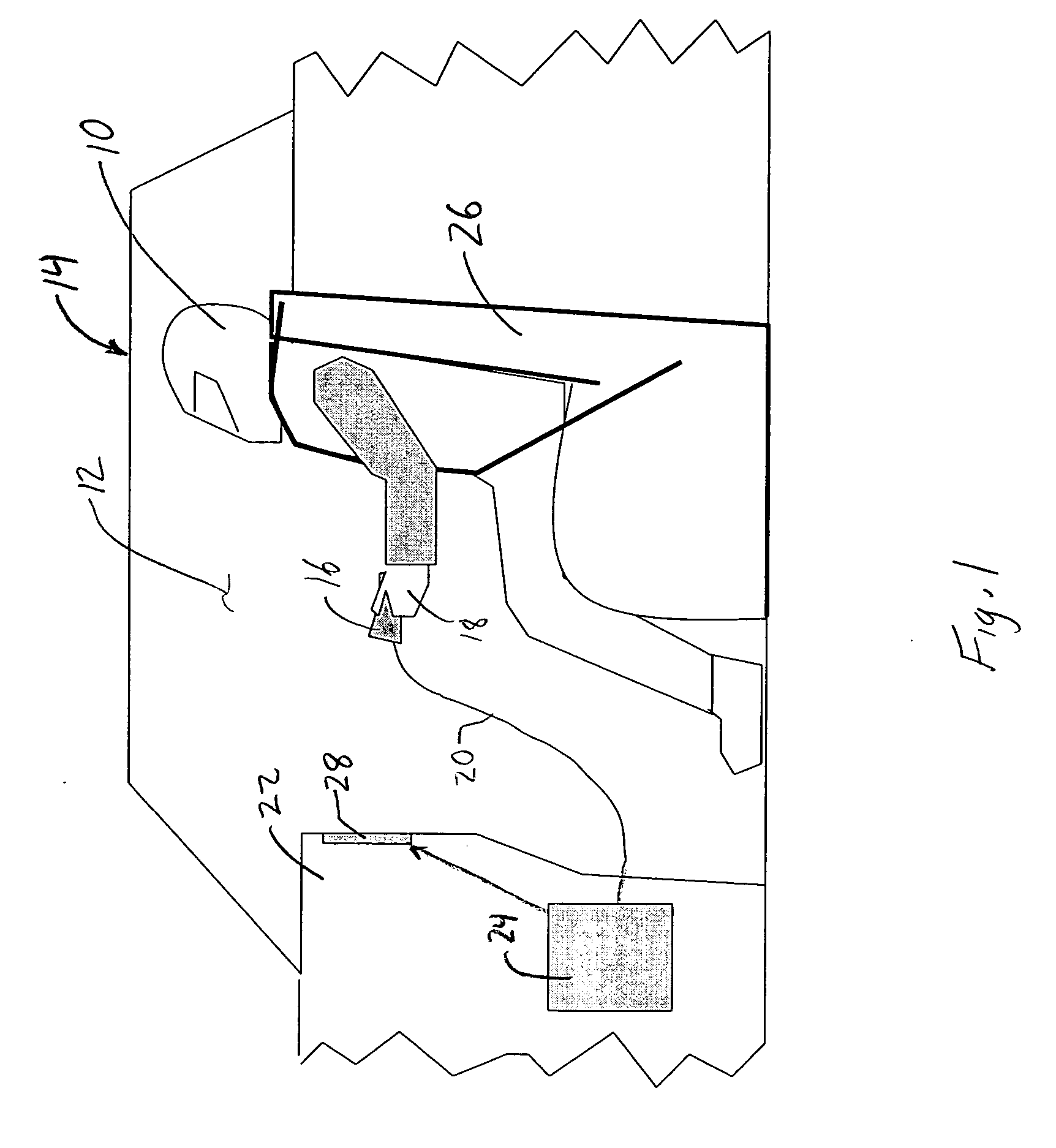
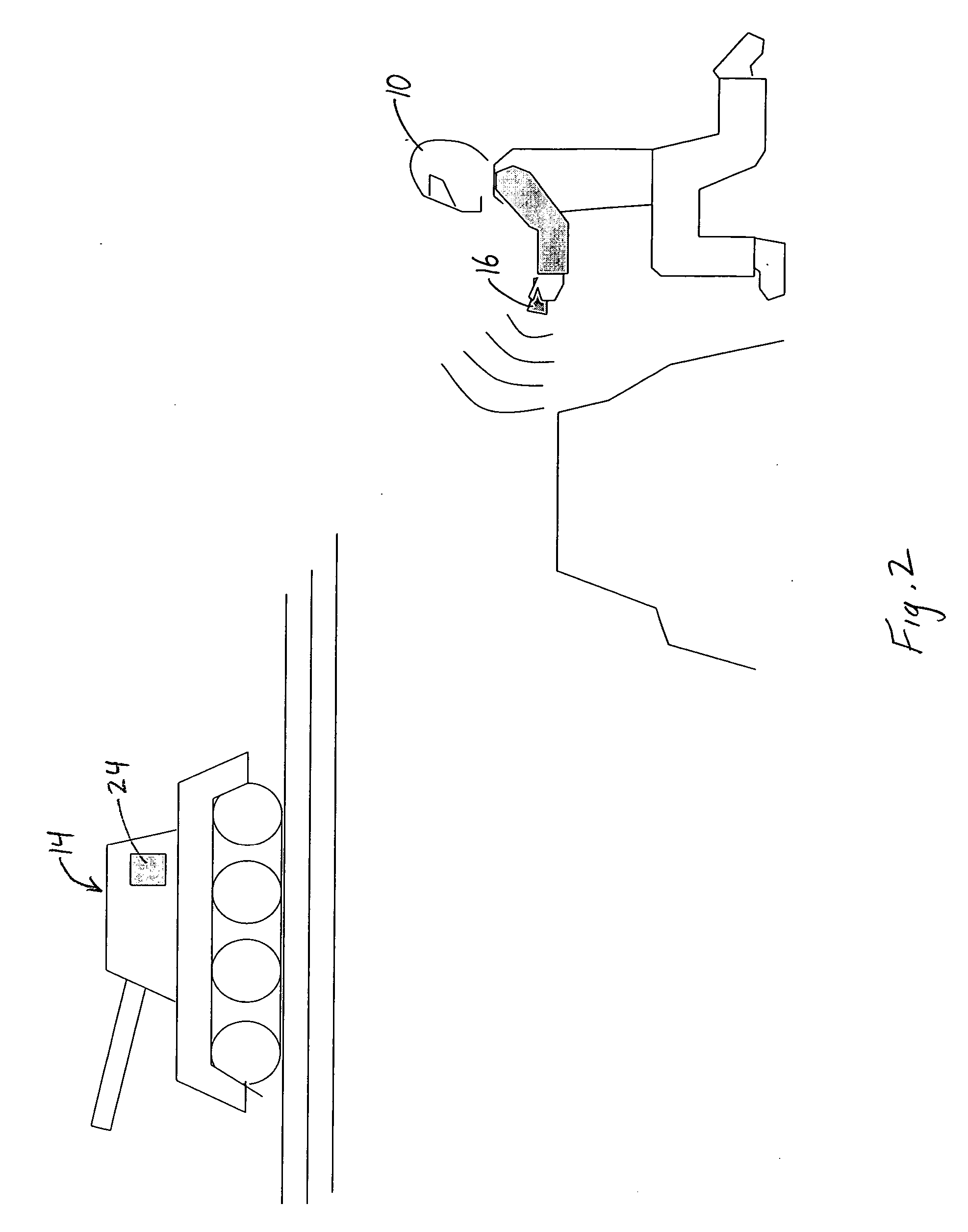
[0020]FIG. 1 depicts a human operator 10 seated within a compartment 12 of a vehicle 14 and controlling various aspects of the vehicle's operation using a handheld controller 16, which is grasped in the hands 18 of the operator 10. As will be described in further detail hereinafter, the operator's fingers are used to manipulate various devices (e.g., buttons, switches, levers, triggers, and the like) to control aspects of the vehicle's operation associated with these devices. In the embodiment shown, the controller 16 is tethered by a cable 20 to a console 22. The cable 20 transmits control signals from the handheld controller 16 to a signal processor 24, which adjusts the various aspects of the vehicle's operation in response to the control signals received from the handheld controller 16. Advantageously, the handheld controller 16 allows the operator 10 to control the various aspects of vehicle operation while fully secured into his or her seat 26. In addition, the cable 20 may be...
PUM
Abstract
A handheld controller allows a human operator to control various aspects of a vehicle's operation. The operator's fingers are used to manipulate various devices (e.g., buttons, switches, joysticks, levers, triggers, trackballs and the like) disposed on the handheld controller to control aspects of the vehicle's operation associated with these devices. The handheld controller may provide control signals to the vehicle by a cable, or by a wireless connection. The handheld controller allows the operator to freely move about the vehicle's compartment or to move outside the compartment, while still being able to control the various aspects of vehicle operation. Furthermore, the handheld controller allows the operator to control the various aspects of vehicle operation from a location away from potentially hazardous surfaces within the compartment, which helps to prevent the operator from contacting these surfaces in the event that the vehicle is struck by an object (e.g., enemy artillery, another vehicle, etc.) or otherwise jarred.
Description
CROSS-REFERENCE TO RELATED APPLICATIONS [0001] This application claims the benefit of U.S. Provisional Patent Application No. 60 / 628,629 filed Nov. 17, 2004, which is incorporate by reference herein in its entirety.BACKGROUND [0002] The present invention is directed to a controller for a vehicle and, more particularly, to a handheld controller for controlling a vehicle. [0003] Modern vehicles, such as for example, automobiles, planes, armored vehicles, helicopters, boats, submarines, and the like, require the vehicle's operator to control many different aspects of the vehicle's operation. This is particularly true of military and law enforcement vehicles, which often require an operator to control equipment related to weaponry, countermeasures, communications, surveillance, and movement (e.g., direction, speed, altitude, depth, etc.) of the vehicle. [0004] In such vehicles, control is typically accomplished through stationary control devices (e.g., buttons, dials, levers, wheels, an...
Claims
Application Information
Patent Timeline
Application Date:The date an application was filed.
Publication Date:The date a patent or application was officially published.
First Publication Date:The earliest publication date of a patent with the same application number.
Issue Date:Publication date of the patent grant document.
PCT Entry Date:The Entry date of PCT National Phase.
Estimated Expiry Date:The statutory expiry date of a patent right according to the Patent Law, and it is the longest term of protection that the patent right can achieve without the termination of the patent right due to other reasons(Term extension factor has been taken into account ).
Invalid Date:Actual expiry date is based on effective date or publication date of legal transaction data of invalid patent.