Capacity detecting sensor
- Summary
- Abstract
- Description
- Claims
- Application Information
AI Technical Summary
Benefits of technology
Problems solved by technology
Method used
Image
Examples
first embodiment
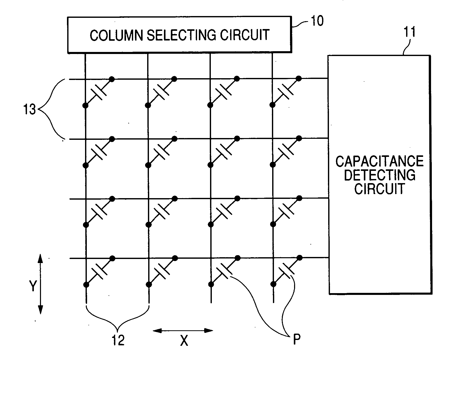
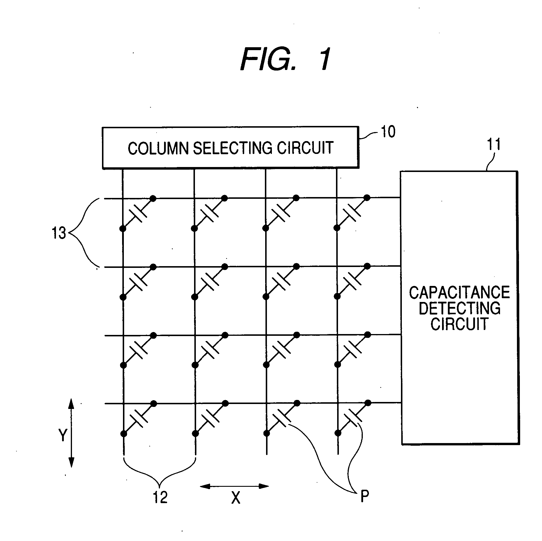
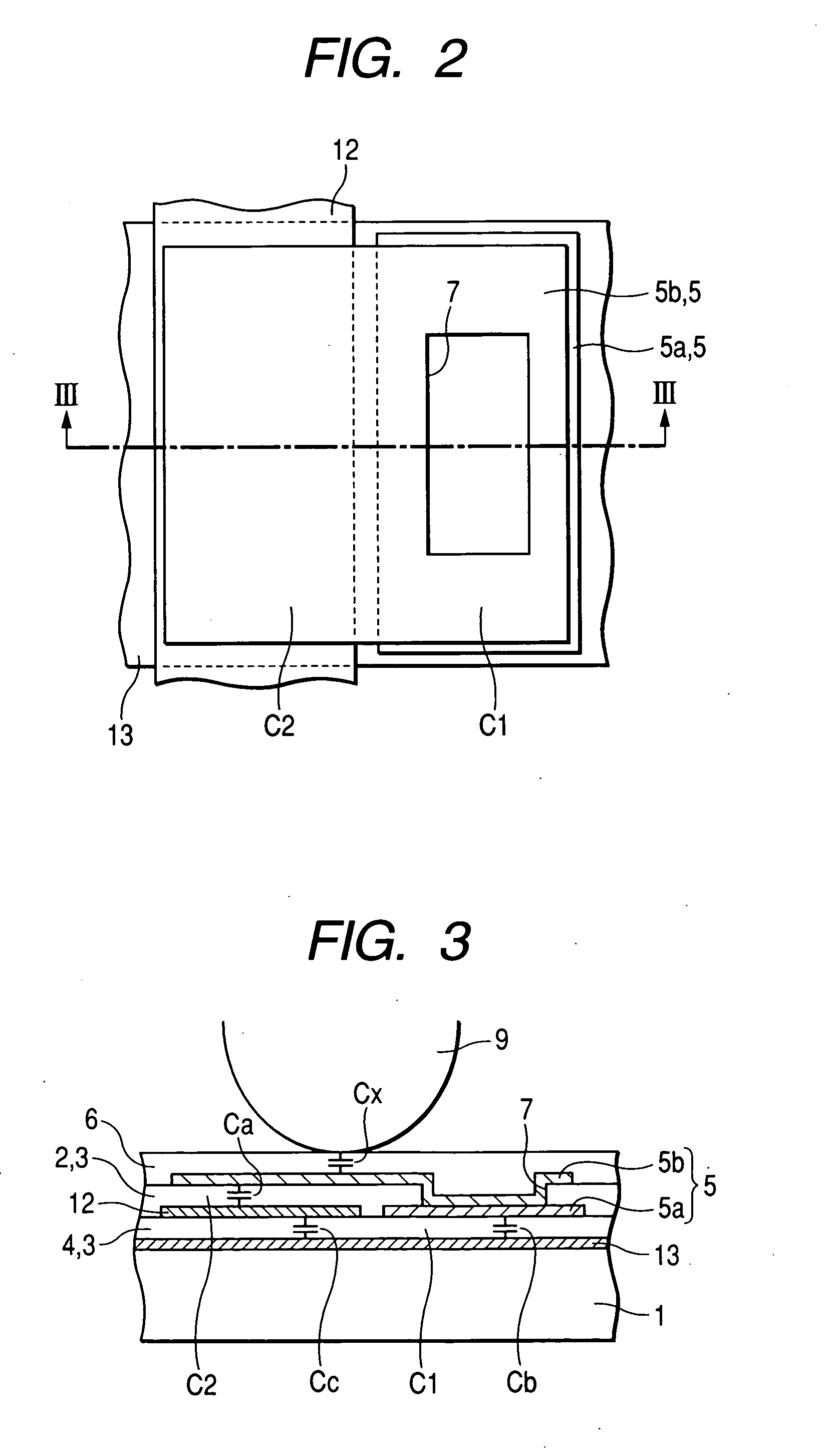
[0035]FIG. 1 is a conceptual view showing a construction of an equivalent circuit of an electrostatic capacity detecting sensor according to a first embodiment of the invention, FIG. 2 is an enlarged plan view of a detecting portion of the capacity detecting sensor of FIG. 1, and FIG. 3 is a cross-sectional view taken along line III-III of FIG. 2.
[0036] The electrostatic capacity detecting sensor according to the embodiment, as shown in FIGS. 1 to 3, includes a plurality of detecting electrodes 13 (first electrode), row wiring lines which are arranged in a first direction X, a plurality of driving electrodes 12 (second electrode), column wiring lines which are arranged in a second direction Y, and a floating electrode 5 (third electrode) which is electrically independent from the detecting electrodes 13 and the driving electrodes 12 through an insulating film 3. The insulating film 3 includes a first interlayer insulating film 4 and a second interlayer insulating film 2. In the ele...
second embodiment
[0070] A second embodiment of the invention will be described with reference to FIGS. 7 to 9. FIG. 7 is an enlarged plan view of a detecting portion of a capacity detecting sensor according to a second embodiment of the invention, FIG. 8 is a cross-sectional view taken along line VIII-VIII of FIG. 7, and FIG. 9 is a cross-sectional view taken along line IX-IX of FIG. 7. The same portions as those of the first embodiment shown in FIGS. 1 to 3 are denoted by the same reference numerals, and thus, their description will be omitted.
[0071] The sensor shown in FIGS. 7 to 9 is different from the first embodiment in that the width a of a detecting electrode 33 composing a region in which the detecting electrode 33 and a driving electrode 12 overlap in a plane is narrower than the width b of the detecting electrode 33 of a region in which the detecting electrode 33 and a driving electrode 12 do not overlap in a plane.
[0072] With the electrostatic capacity detecting sensor like the above, a...
third embodiment
[0074] A third embodiment of the invention will be described with reference to FIG. 10. FIG. 10 is a cross-sectional view of a detecting portion of a capacity detecting sensor according to a third embodiment of the invention. Meanwhile, in the capacity detecting sensor of the third embodiment according to the invention, the shapes of the respective members viewed in plan are almost the same as FIG. 2, and FIG. 10 is a cross-sectional view taken along line A-A of FIG. 2. In addition, in the third embodiment shown in FIG. 10, the same portions as those of the first embodiment shown in FIGS. 1 to 3 are denoted by the same reference numerals, and thus, their description will be omitted.
[0075] The sensor shown in FIG. 10 is different from the first embodiment in that a driving electrode 12 is composed of a third conductive film, and the floating electrode 5 is formed between a detecting electrode and the driving electrode 12 through an insulating film 3 by arranging a lower electrode 5a...
PUM
 Abstract
Description
Claims
Application Information
 - R&D
- Intellectual Property
- Life Sciences
- Materials
- Tech Scout
- Unparalleled Data Quality
- Higher Quality Content
- 60% Fewer Hallucinations
Browse by: Latest US Patents, China's latest patents, Technical Efficacy Thesaurus, Application Domain, Technology Topic, Popular Technical Reports.
© 2025 PatSnap. All rights reserved.Legal|Privacy policy|Modern Slavery Act Transparency Statement|Sitemap|About US| Contact US: help@patsnap.com


