Keyboard module with light-emitting array and key unit thereof

a keyboard module and array technology, applied in the field of input devices, can solve the problems of not easily readable printed characters on the key units, unfavorable user operation, easy wear and tear of keys, etc., and achieve the effects of convenient operation, easy readable key units, and easy wear and tear of characters

Inactive Publication Date: 2006-06-08
MITAC TECH CORP
View PDF10 Cites 57 Cited by
  • Summary
  • Abstract
  • Description
  • Claims
  • Application Information

AI Technical Summary

Benefits of technology

[0016] With the technical means adopted in the present invention, a conveniently operable keyboard with easily readable key unit is provided to solve the problems existed in the conventional keyboards, including dazing and easily worn off characters printed on small key units, and key functions that must be identified according to the operating mode currently in use.
[0017] The light-emitting element array below each key unit provides an illuminant character on the key unit each time, allowing a user to correctly identify the function of the key unit even in a dim environment. In other words, ...

Problems solved by technology

However, the key units with so many different characters marked thereon tend to daze the user while operating the keyboard.
Such printed characters on the key units are not easily readable when the keyboard is used in a dim envir...

Method used


Image

  • Keyboard module with light-emitting array and key unit thereof
  • Keyboard module with light-emitting array and key unit thereof
  • Keyboard module with light-emitting array and key unit thereof

Examples


first embodiment

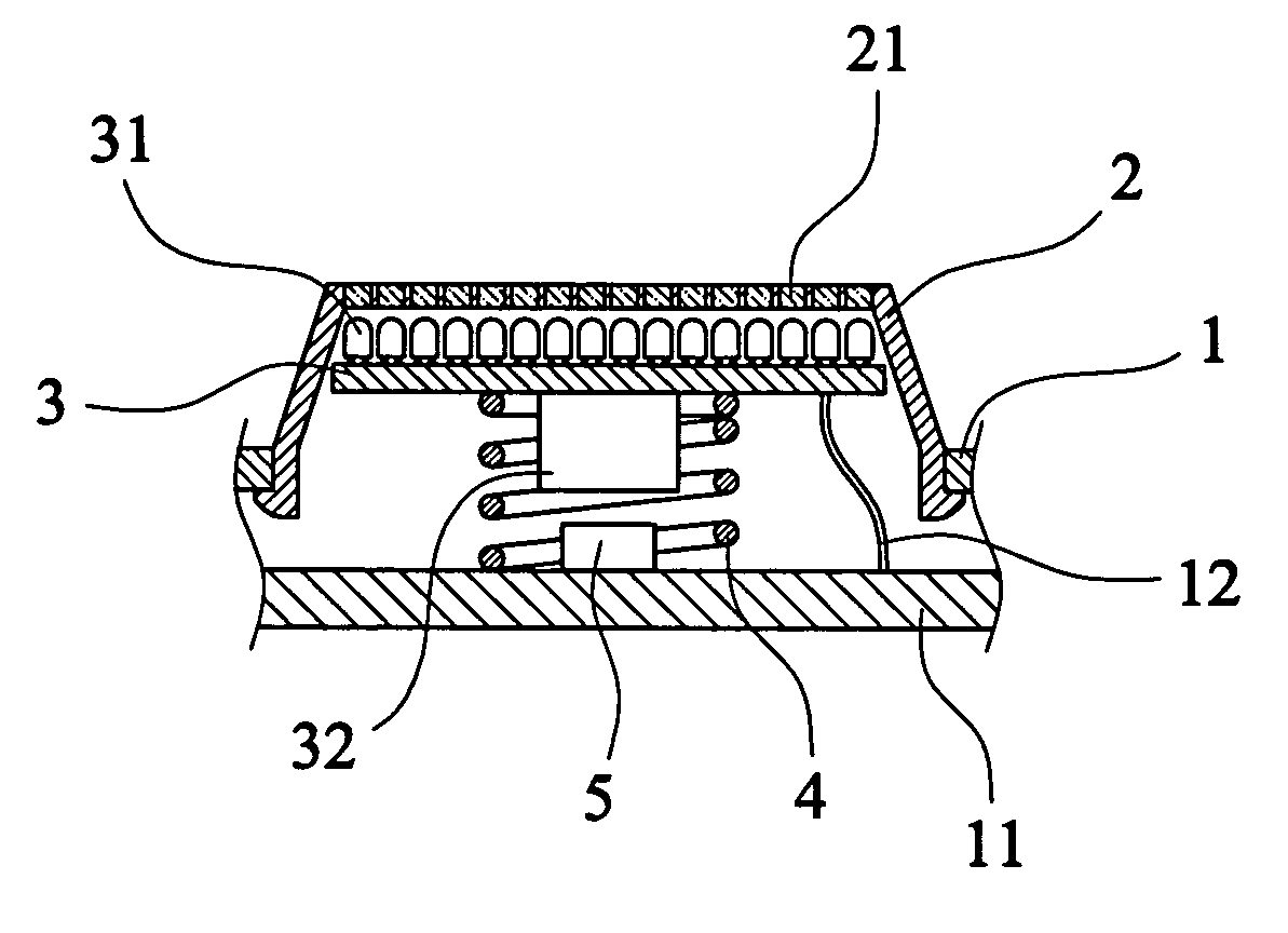
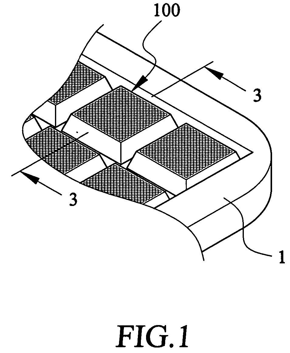
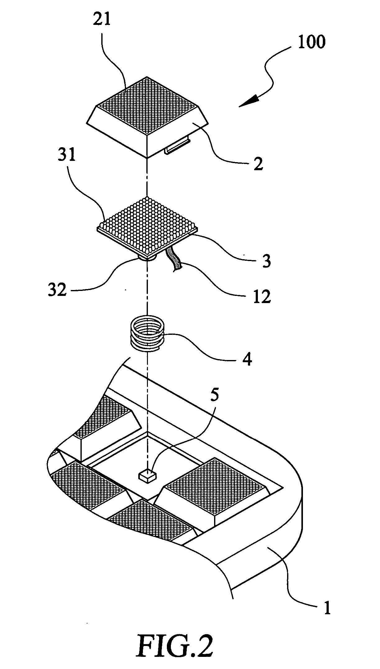
[0028] Please refer to FIG. 1 that is a fragmentary perspective view of a keyboard module using light-emitting array to show character on key unit thereof according to the present invention, and to FIG. 2 that is an exploded perspective view of a key unit of the keyboard module according to the present invention. As shown, the keyboard module, which is generally denoted with a reference numeral 1, includes a plurality of key units 100 arranged on a case of the keyboard module 1. Each of the key units 100 is provided on a top surface with one character each time for a user to identify the meaning and function of that key unit 100.

[0029]FIG. 3 is a sectional view taken along line 3-3 of FIG. 1. Please refer to FIGS. 1, 2, and 3 at the same time. In the first embodiment of the present invention, each key unit 100 includes a cap member 2 located at the top thereof for a user to depress and thereby input data. The cap member 2 is formed of a plurality of light transmittable areas 21 set ...

second embodiment

[0034] The cap member 2 of each key unit 100 in the second embodiment is formed of a plurality of arrayed receiving holes 22. A plurality of light-emitting elements 31 are arrayed on a light-emitting element substrate 3, such that each of the light-emitting elements 31 is aligned with and received in one receiving hole 22 on the cap member 2. A protective cover 23 is attached to the top surface of the cap member 2.

[0035] In the second embodiment, there is also a downward extended post 32 provided at a bottom side of the light-emitting element substrate 3 for a restoring spring 4 to mount therearound, and a key switch 5 is provided on the circuit substrate 11 in the keyboard 1 corresponding to the post 32. Again, the circuit substrate 11 is electrically connected to the light-emitting element substrate 3 via a signal line 12.

[0036] The restoring spring 4 normally pushes the cap member 2 of the key unit 100 upward. When the cap member 2 is depressed, the downward extended post 32 bel...


PUM


Abstract

A keyboard module includes a plurality of key units, each of which is provided below a cap member thereof with an array of light-emitting elements. Under the control of a keyboard control circuit in the keyboard module, the light-emitting elements below each cap member are selectively driven to emit light, which is projected toward the cap member to show a specific character on a top surface of the cap member. A key switch is located below the cap member and is actuated to generate and send a key signal to the keyboard control circuit when the cap member is depressed.

Description

FIELD OF THE INVENTION [0001] The present invention relates to an input device with easily readable characters provided thereon, and more particularly to a keyboard module using light-emitting array to show character on key unit thereof. BACKGROUND OF THE INVENTION [0002] A variety of apparatus, such as computers, measuring instruments, control devices, digital devices, office automation equipment, etc., are equipped with a keyboard for inputting data. By way of example, the keys on the keyboards of the currently available computers can be structurally divided into two types, namely, mechanical spring keys and silicon rubber membrane keys. [0003] The keyboards for the current computers generally include a case, on which a plurality of key units are arranged. Each of these key units is provided at a top thereof with one or more figures, symbols, letters, and / or characters for a user to identify the meaning and function of that key unit during operation. [0004] Each of the key units o...

Claims


Application Information

Patent Timeline
IPC IPC(8): G06F3/023
CPCG06F3/0202G06F3/0238
Inventor CHANG, CHIH-CHING
Owner MITAC TECH CORP
Why Eureka
Try Eureka