Noise canceling differential connector and footprint

a technology of differential connectors and noise cancelling, applied in the direction of coupling device details, coupling device connections, printed circuits, etc., can solve the problems of increasing the footprint or the size of the electrical connector, increasing the cost of the connector,

Active Publication Date: 2006-06-08
TYCO ELECTRONICS LOGISTICS AG (CH)
View PDF14 Cites 53 Cited by
  • Summary
  • Abstract
  • Description
  • Claims
  • Application Information

AI Technical Summary

Problems solved by technology

However, the addition of numerous ground shields may increase the cost of the connector.
Furthermore, the f

Method used


Image

  • Noise canceling differential connector and footprint
  • Noise canceling differential connector and footprint
  • Noise canceling differential connector and footprint

Examples


Embodiment Construction

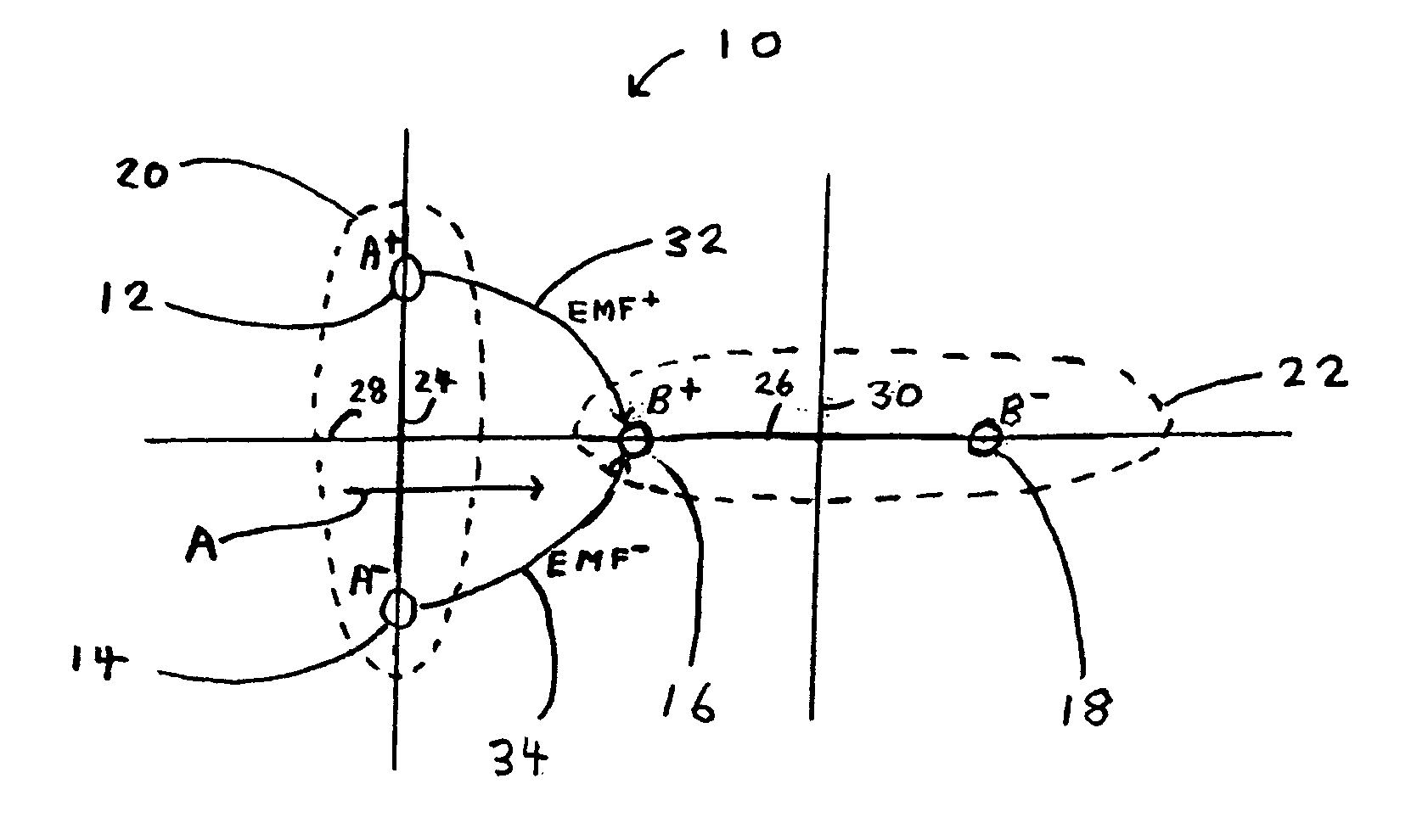
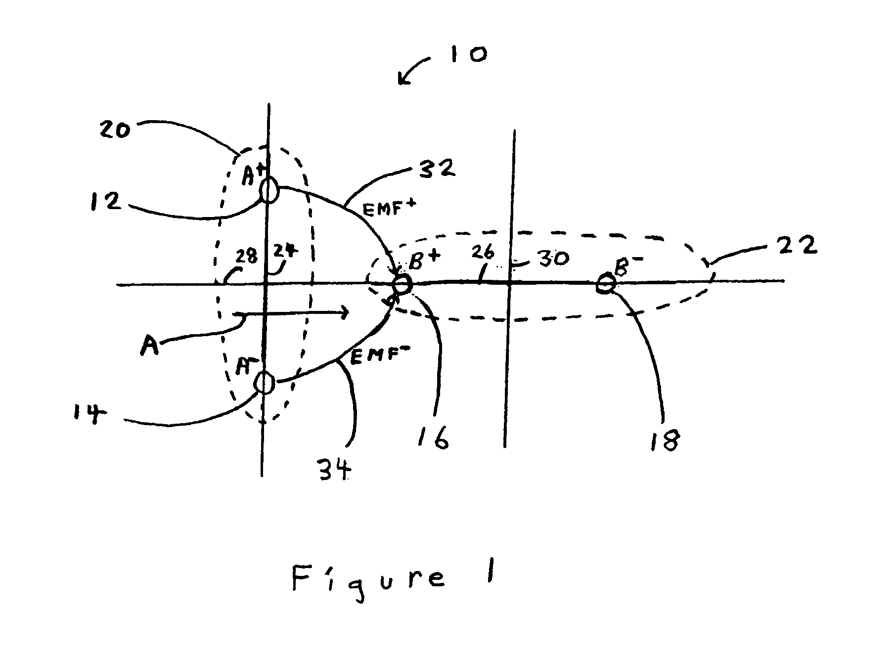
[0014]FIG. 1 illustrates a contact pattern 10 of an electrical connector formed in accordance with an embodiment of the present invention. The contact pattern 10 is oriented to reduce the cross talk / noise of plated through-holes in the electrical connector. Contact pattern 10 shows four contacts 12, 14, 16, and 18, which may be included in a mating interface of a housing of an electrical connector. FIG. 1 illustrates a differential pair 20 and a differential pair 22 arranged orthogonal to one another. The differential pair 20 includes the contacts 12 and 14 that are configured to carry differential signal “A”. The differential signal “A” is comprised of an “A+” component (contact 12) and an “A−” component (contact 14), each component an inverse of the other. Likewise, the differential pair 22 includes the contacts 16 and 18 that are configured to carry a differential signal “B”. The differential signal “B” is comprised of a “B+” component (contact 16) and a “B−” component (contact 1...


PUM


Abstract

An electrical connector is provided that includes a housing having a mating interface. Contacts provided in the housing are organized in differential pairs with the contacts in each of the differential pairs being located along an associated differential pair contact line. The differential pairs are aligned wherein the differential pair contact lines of adjacent differential pairs are non-parallel to one another.

Description

BACKGROUND OF THE INVENTION [0001] This invention relates generally to electrical connectors and more particularly, to differential pair electrical connectors. [0002] A variety of connectors exist today for use in differential pair applications. In differential pair applications, a signal is divided in half (each half being the inverse of the other half) and each half is transmitted over a separate data line to a mating interface of a connector. The mating interface of an electrical connector may have a plurality of contacts, and in differential pair applications, the contacts are generally organized into differential pairs. The signal quality of a differential pair of contacts may be reduced due to cross talk / noise and the like caused by electromagnetic fields (EMFs) created by nearby differential pairs of contacts. The structure and configuration of an electrical connector affects the cross talk aspects of the electrical connector. The electronics industry has offered various solu...

Claims


Application Information

Patent Timeline
IPC IPC(8): H05K1/00
CPCH01R13/6461
Inventor FOGG, MICHAEL W.
Owner TYCO ELECTRONICS LOGISTICS AG (CH)
Why Eureka
Try Eureka