Spline Stress Distribution

a stress distribution and spline technology, applied in the direction of couplings, rod connections, manufacturing tools, etc., can solve the problems of affecting the design of shaft connections, affecting the performance of shafts, and affecting the design of shafts. the effect of stress concentration and reducing torqu

Inactive Publication Date: 2010-12-02
BAKER HUGHES INC
View PDF28 Cites 36 Cited by
  • Summary
  • Abstract
  • Description
  • Claims
  • Application Information

AI Technical Summary

Benefits of technology

[0010]A connection between a shaft and a coupling that preferably involves involute shaped splines is designed to reduce stress from torque applied to the shaft by a drive motor. To avoid stress concentration at the mouth of the coupling on startup, the shaft splines are made to taper from the shaft end down to the spline end. As a result, the initial contact with the coupling splines occurs within the coupling and removed from it mouth. The shaft is allowed to elastically twist in response to the applied torque as the contact area increases with shaft twisting and the contact line moves toward the mouth of the coupling. Stress concentration that formerly occurred at the coupling mouth is alleviated as some shaft elastic twist occurs without adding stress to the shaft splines until coupling contact is made.

Problems solved by technology

Equipment designed to fit in bore holes is, by nature, long and slim.
Torsional loading of the shafts is often a limiting factor in the maximum power developed.
Shaft connections are critical weak points in the shaft designs.
This is reaching the limits of readily available materials.
The selected materials are therefore more brittle and more susceptible to fatigue in the areas of high stress concentration.
The problem of the spline joint is, when under load, the coupling which is stiffer will twist much less than the shaft.
This is impractical because the coupling thickness is necessary to counter the radial forces that are attempting to expand (explode) the coupling.
The coupling is formed by a pull broach, and it would be an extremely difficult operation to create a coupling spline that was wider at the start (mouth) of the coupling and taper as it progressed inward.
Increasing the compliance of the coupling by reducing its diameter is impractical because it increases the radial stress in the coupling from the radial component of the torque developed by the spline tooth.
The coupling could fail from expansion (explosion).
Basically a large amount of tedious work is required for the benefit achieved.

Method used


Image

  • Spline Stress Distribution
  • Spline Stress Distribution
  • Spline Stress Distribution

Examples


Embodiment Construction

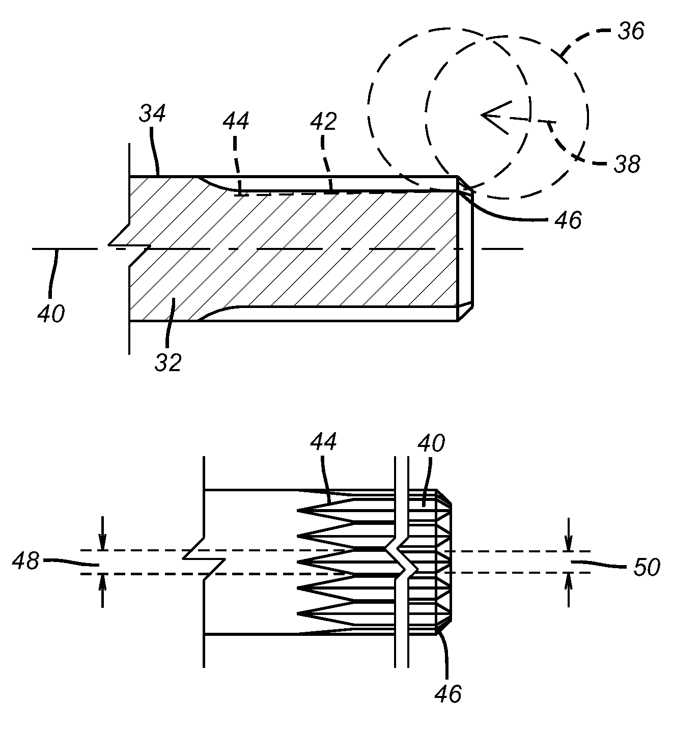
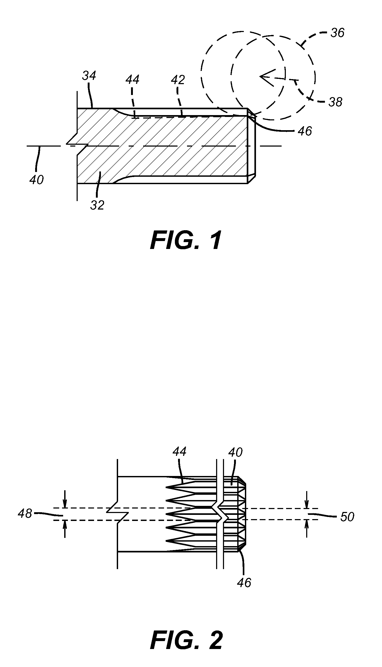
[0018]The situation addressed by the present invention is shown in FIG. 3. Shaft 10 has a motor end 12 and a coupling end 14. A coupling 16 connects a driven shaft 18 to the driving shaft 10. Shaft 10 rotates in the direction of arrow 20. As shown in the enlarged view shaft male spline 22 (only one of which is shown for clarity) is preferably an involute shape in section having opposed base edges 24 and 26 that are parallel to each other. The female spline 28 has the same profile as spline 22. As a result, when the motor (not shown) is started and shaft 10 begins to turn, the maximum stress from the applied torque is located at the mouth 30 of the coupling 16 as indicated by the arrow pointing to the leading face of the spline 22 in the direction of rotation 20. This concentration of bending stress at the mouth 30 of the coupling can crack or fracture the splines 22 at the mouth 30 location of the coupling 16. The present invention seeks to reduce the degree of stress at the mouth 3...


PUM


Abstract

A connection between a shaft and a coupling that preferably involves involute shaped splines is designed to reduce stress from torque applied to the shaft by a drive motor. To avoid stress concentration at the mouth of the coupling on startup, the shaft splines are made to taper from the shaft end down to the spline end. As a result, the initial contact with the coupling splines occurs within the coupling and removed from it mouth. The shaft is allowed to elastically twist in response to the applied torque as the contact area increases with shaft twisting and the contact line moves toward the mouth of the coupling. Stress concentration that formerly occurred at the coupling mouth is alleviated as some shaft elastic twist occurs without adding stress to the shaft splines until coupling contact is made.

Description

FIELD OF THE INVENTION[0001]The field of the invention is the connection between a shaft and a coupling and more particularly in the context of downhole equipment where the shaft is splined and the splines are configured for stress distribution.BACKGROUND OF THE INVENTION[0002]Equipment designed to fit in bore holes is, by nature, long and slim. Torsional loading of the shafts is often a limiting factor in the maximum power developed. Shaft connections are critical weak points in the shaft designs. The preferred choice for shaft connection in an Electrical Submersible Pump (ESP) is a spline, either a multi tooth involute, or six tooth square spline. Both have proved to be quick and reliable for field assembly of the equipment. Shaft material strength requirements for high power units can exceed 200,000 PSI yield. This is reaching the limits of readily available materials. To achieve these strength levels, elongation (ductility) has to be sacrificed. The selected materials are theref...

Claims


Application Information

Patent Timeline
Patent Type & Authority Applications(United States)
IPC IPC(8): F16D1/06
CPCF16D1/101F16D2001/103Y10T403/1624Y10T403/7026F16D1/02F16D3/10
Inventor BROWN, DONN J.WILSON, BROWN L.
Owner BAKER HUGHES INC
Why Eureka
Try Eureka