Materialized view maintenance and change tracking

Active Publication Date: 2006-06-08
ORACLE INT CORP
View PDF18 Cites 70 Cited by
  • Summary
  • Abstract
  • Description
  • Claims
  • Application Information

AI Technical Summary

Benefits of technology

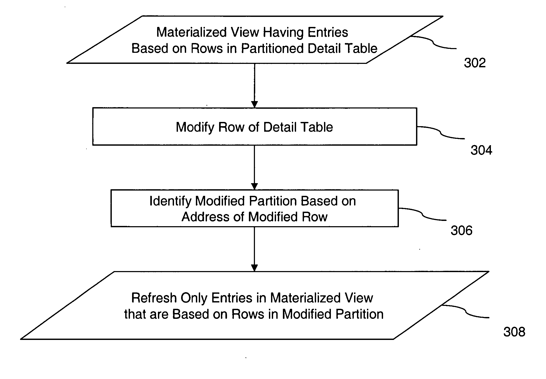
[0031] Another aspect of the invention pertains to a method for maintaining a materialized view having entries based on rows in a detail table. The detail table is partitioned into a plurality of partitions based on corresponding lists of discrete values, wherein each of the rows belongs to a single one of the partitions. A row in the detail table is modified, and a modified partition from among the partitions that the modified row belongs to is identified. Only the entries in the materialized view that are based on the rows that belong to the modified partition are refreshed.
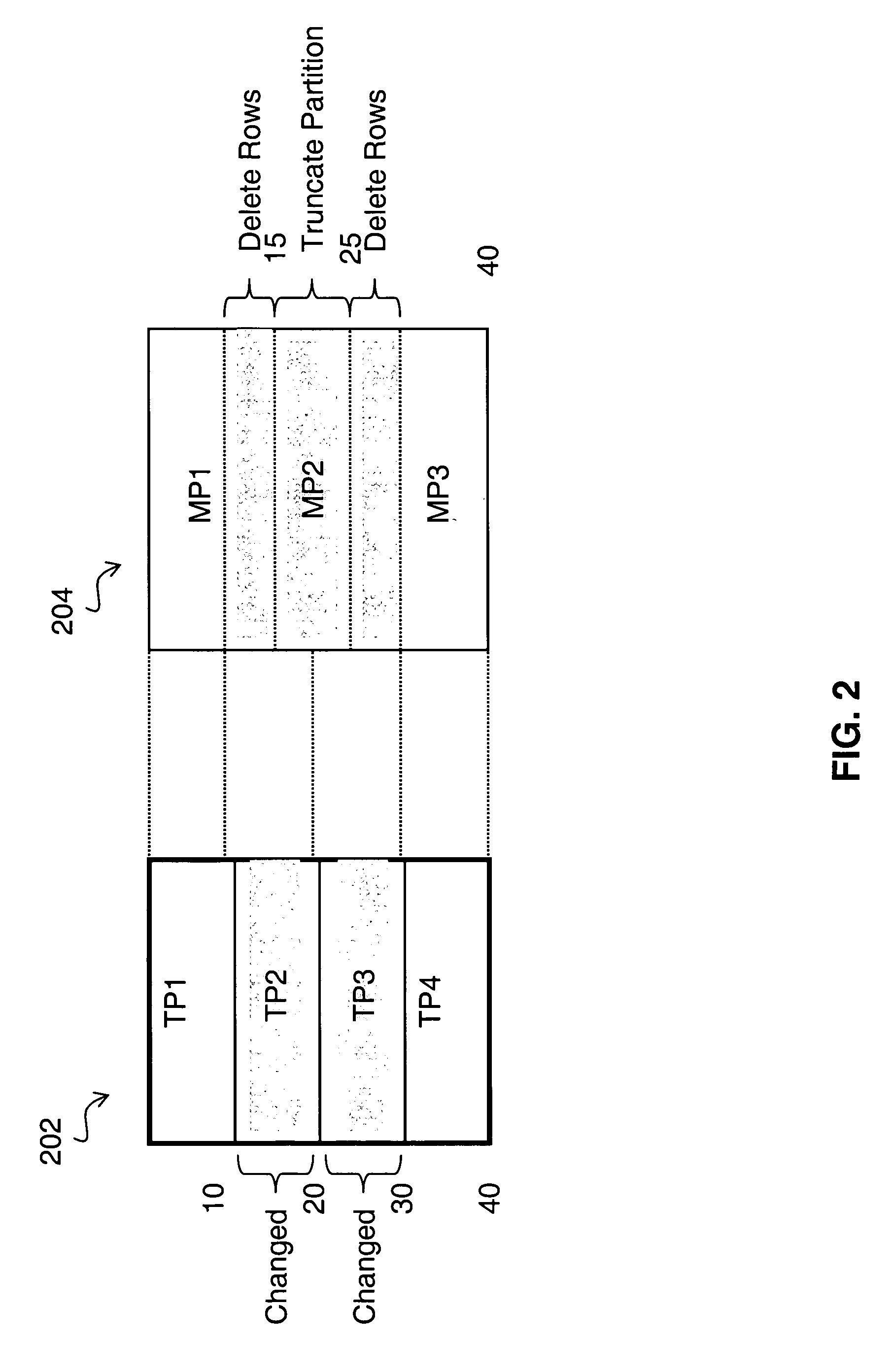
[0032] Still another aspect of the invention involves a method for maintaining a materialized view having entries based on rows in a detail table. The detail table is partitioned into a plurality of first partitions based on a key, wherein each of the rows belongs to a single one of the first partitions. The materialized view is partitioned into a plurality of second partitions based on the key, wherein each of the entries belongs to a single one of the second partitions. One of the rows in the detail table is modified. A modified partition from among the first partitions that contains the modified row is identified. At least one of the second partitions that contain one or more entries in the materialized view that are based on rows that belong to the modified partition is identified. All the entries in the at least one of the second partitions are deleted. According to one embodiment, the entries of the at least one of the second partitions are recalculated.
[0033] Yet another

Problems solved by technology

Conventionally, the materialized view was “atomic” and treated as an inseparable object so that the status of its data could only be either globally fresh or globally stale, which has been a drawback that has affected the availability of the materialized view.
For example, when any of the detail tables of the materialized view were updated, the materialized view immediately became globally “stale.” All the data in the materialized view became distrusted and unusable in the query rewrite (unless lowering the confidence level) since there was no easy way to identify which part of the data was affected by the changes.
However, the row-change-based incremental refresh has limitations.
For example, when the detail table is partitioned (e.g., by range or list of values) and a partition maintenance operation (e.g., exchange partitions) occurs, the conventional row-based in

Method used


Image

  • Materialized view maintenance and change tracking
  • Materialized view maintenance and change tracking
  • Materialized view maintenance and change tracking

Examples


Embodiment Construction

[0041] A system, method, and software for materialized view maintenance and change tracking are described. In the following description, for the purposes of explanation, numerous specific details are set forth in order to provide a thorough understanding of the present invention. It is apparent, however, to one skilled in the art that the present invention may be practiced without these specific details or with an equivalent arrangement. In other instances, well-known structures and devices are shown in block diagram form in order to avoid unnecessarily obscuring the present invention.

[0042] In a database management system, data is stored in one or more data containers, each container contains records, and the data within each record is organized into one or more fields. In relational database systems, the data containers are referred to as tables, the records are referred to as rows, and the fields are referred to as columns. In object-oriented databases, the data containers are r...


PUM


Abstract

A technique for refreshing materialized views in a database is disclosed. The detail table is partitioned, and changes made to the detail table are tracked with information stored, for example. Only sections in the materialized view which correspond to the partitions which include modifications made to the detail table are refreshed, thus avoiding the need of a complete refresh to overcome staleness.

Description

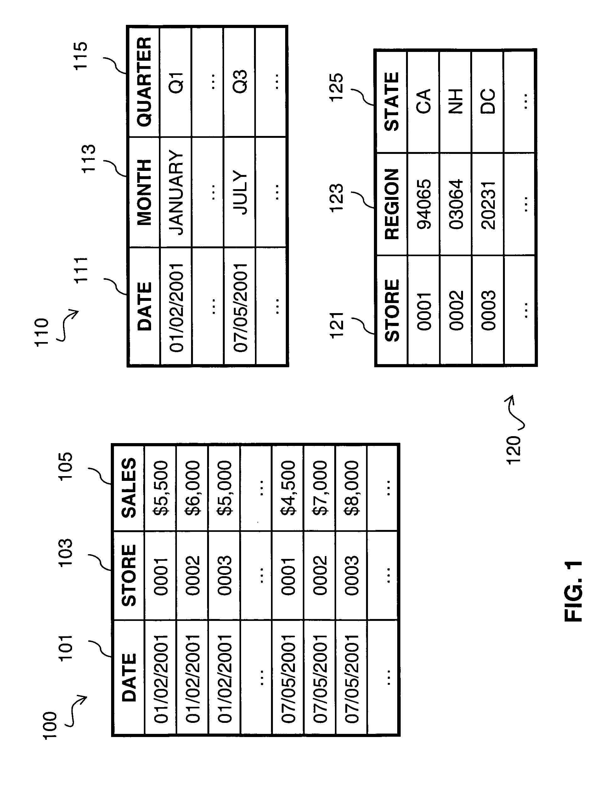
FIELD OF THE INVENTION [0001] The present invention relates to computer database systems and more particularly to materialized view maintenance and change tracking. BACKGROUND OF THE INVENTION [0002] Relational databases store information in collections of tables, in which each table is organized into rows and columns. A popular application of relational database technology is data warehousing, in which an organization's data repository is designed to support the decision-making process for the organization. [0003]FIG. 1 illustrates an exemplary database containing three tables, a sales table 100, a time table 110, and a store table 120, useful for recording and organizing information about a company's sales operation. In this example, the sales table 100 is a fact table, and the time table 110 and the store table are dimension tables. The columns of the sales table 100 hold attributes for the sales made by the company, including the date in a date column 101, the store identifier i...

Claims


Application Information

Patent Timeline
IPC IPC(8): G06F17/30
CPCG06F17/30383G06F16/2393
Inventor YU, TSAE-FENGRAITTO, JOHNPANCHAPAGESAN, BHUJANGALAWANDE, SHILPABELLO, RANDALL G.
Owner ORACLE INT CORP
Why Eureka
Try Eureka