Transition-to-turbine seal apparatus and kit for transition/turbine junction of a gas turbine engine

a gas turbine engine and seal device technology, applied in the field of gas turbine engines, can solve problems such as inability to meet the requirements of installation,

Active Publication Date: 2006-06-15
SIEMENS ENERGY INC
View PDF31 Cites 119 Cited by
  • Summary
  • Abstract
  • Description
  • Claims
  • Application Information

AI Technical Summary

Problems solved by technology

Consequently, the design of such seal has presented a challenge that resulted in various approaches that attempt to find a suitable balance between seal cost, reliability, durability, installation and repair ease, performance, and effect on adjacent components.
However, these are considered to involve unacceptable risks of failure or excessive wear, and / or difficulties with installation.

Method used


Image

  • Transition-to-turbine seal apparatus and kit for transition/turbine junction of a gas turbine engine
  • Transition-to-turbine seal apparatus and kit for transition/turbine junction of a gas turbine engine
  • Transition-to-turbine seal apparatus and kit for transition/turbine junction of a gas turbine engine

Examples


Embodiment Construction

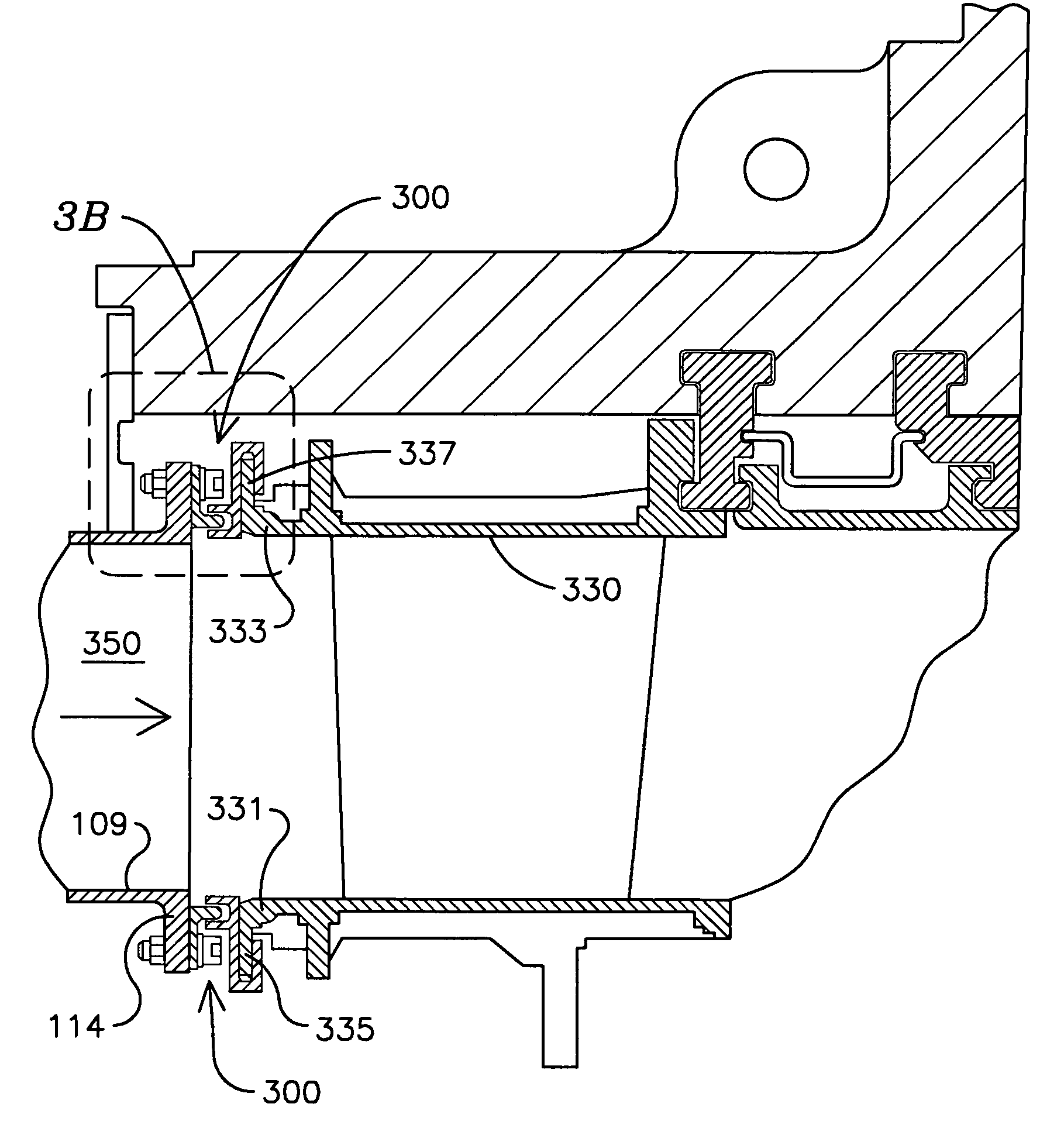
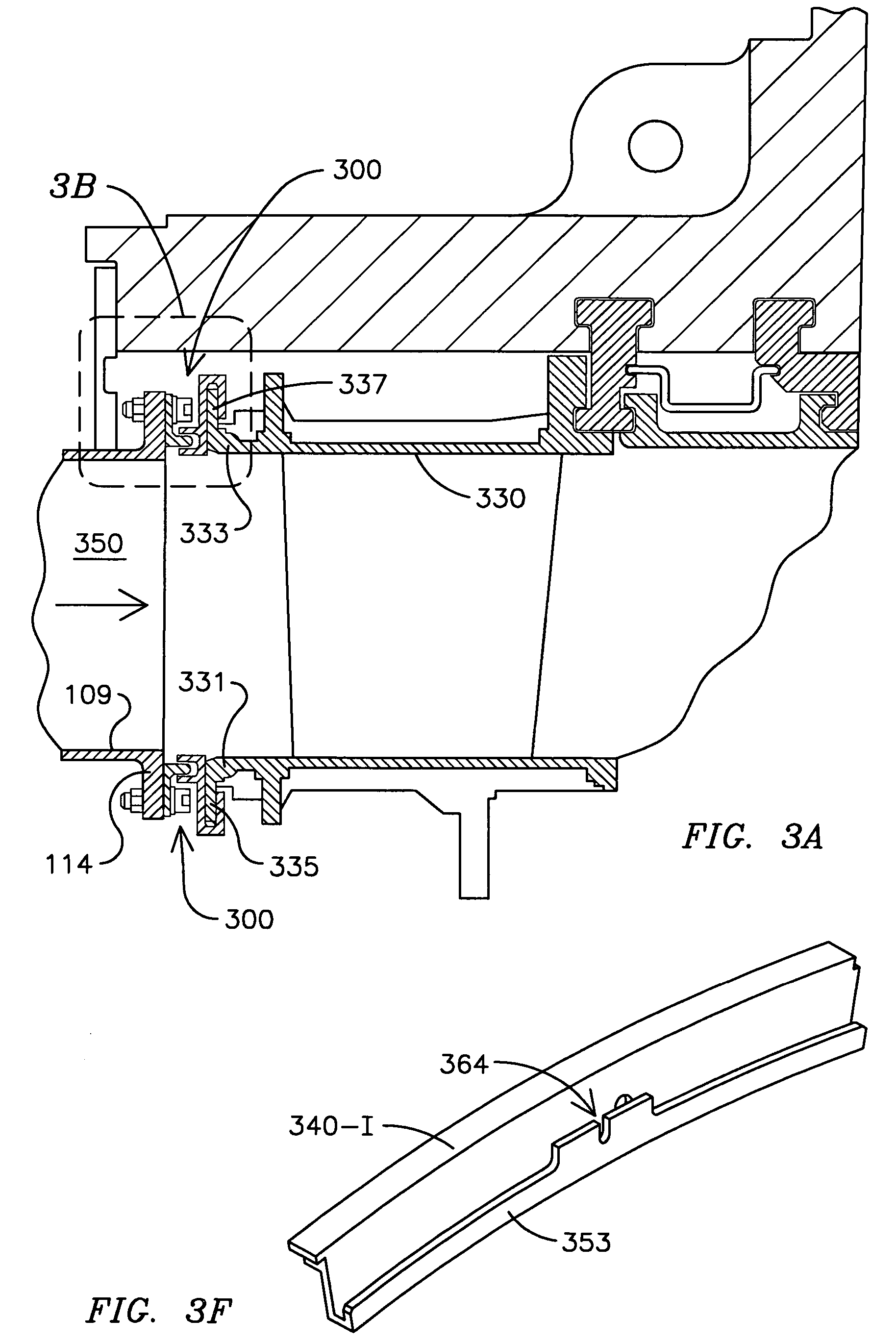
[0014] Embodiments of the invention provide a number of advances over known transition-to-turbine seals, providing enhanced durability and lower wear rates of adjacent components. For example, in contrast to the approach of U.S. Pat. No. 5,749,218, to utilize harder metal inserts in a transition U-shaped slot, embodiments of the present invention eliminate wear on the transition at the seal interface. Also, various embodiments comprise consumable seal components that are relatively softer than more costly, adjacent parts. Motivation to preserve these adjacent parts (e.g., the transition and the row 1 vane segments) has become greater with the trend to increase firing temperature of gas turbine engines. Such increases in firing temperature are related to achieving desired emissions and operational efficiencies.

[0015] One approach is to construct components along the path of hot gases to have greater durability at higher temperatures, and this increases the cost of such components. F...


PUM


Abstract

One embodiment of a transition-to-turbine seal (300) comprises a transition exit seal (302) adapted for fixed attachment to an exit rail (116) of a transition (109), and a stage-1 seal (340). The stage-1 seal (340) comprises an axial seal slot (348) comprising parallel walls (346, 347) adapted to slidingly engage a first male member (310) of the transition exit seal (302). The stage-1 seal (340) also comprises a radial seal slot (354) comprising parallel walls (351, 353) adapted to slidingly engage a plate (338) of a row 1 vane segment (330). The transition-to-turbine seal (300) thus provides both axial and radial freedom of movement. Materials and coatings for the transition exit seal (302) and the stage-1 seal (340) are selected to promote preferential wear of these components relative to wear of the surface of the row 1 vane segment (330). Wear of the exit rail (116) is reduced or eliminated due to the noted fixed attachment.

Description

RELATED APPLICATIONS [0001] This application claims the benefit of U.S. Provisional Application No. 60 / 635,028, filed Dec. 10, 2004. This provisional application is incorporated by reference.FIELD OF INVENTION [0002] The invention generally relates to a gas turbine engine, and more particularly to a seal between a transition and a turbine of such engine. BACKGROUND OF THE INVENTION [0003] In gas turbine engines, air is compressed at an initial stage, then is heated in combustion chambers, and the hot gas so produced passes to a turbine that, driven by the hot gas, does work which may include rotating the air compressor. [0004] In a typical industrial gas turbine engine a number of combustion chambers combust fuel and hot gas flowing from these combustion chambers is passed via respective transitions (also referred to by some in the field as ducts) to respective entrances of the turbine. More specifically, a plurality of combustion chambers commonly are arranged radially about a long...

Claims


Application Information

Patent Timeline
Patent Type & Authority Applications(United States)
IPC IPC(8): F23R3/42
CPCF01D9/041F01D11/005F16J15/062F16J15/0887F05D2240/55
Inventor ZBOROVSKY, JAMES M.HSU, JOHANMCQUIGGAN, ANDREW G.
Owner SIEMENS ENERGY INC
Why Eureka
Try Eureka