
Contactless input device

a contactless input and input device technology, applied in the field of contactless input devices, can solve the problems of limiting the choices available to users, affecting the use of users, and most conventional input devices suffering from drawbacks, so as to give users more flexibility and convenien

Inactive Publication Date: 2006-06-15
KONINKLIJKE PHILIPS ELECTRONICS NV
View PDF7 Cites 25 Cited by
  • Summary
  • Abstract
  • Description
  • Claims
  • Application Information

AI Technical Summary

Benefits of technology

The present invention provides an input device that allows users to move in a 3D space without needing a flat surface. The device has a motion detection sensor that generates 3D motion data, which is transmitted to a computer to determine the distance and direction of movement. The computer then moves a cursor to a corresponding position based on the motion data. The device also generates control signals in response to user commands, including left and right click operations, double click operations, and click and drag operations. This invention provides users with more flexibility and convenience than traditional input devices.

Problems solved by technology

At present, most conventional input devices suffer from drawbacks.
This limits the choices available to the users.
This can cause much inconvenience for the user while standing in the middle of the room, giving the presentation or lecture.

Method used


Image

  • Contactless input device
  • Contactless input device
  • Contactless input device

Examples


first embodiment

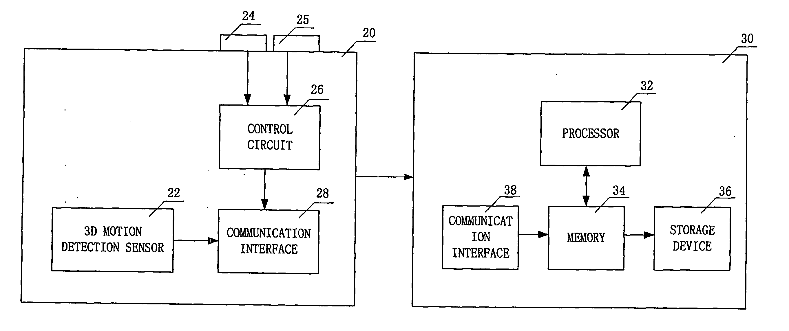
[0017]FIG. 1 shows an input device 20 connected to a computer 30 according to the invention. As illustrated, input device 20 includes a three-dimensional (3D) motion detection sensor 22, left and right control buttons 24 and 25, a control circuit 26, and a communication interface 28. Computer 30 includes a processor 32, a memory 34, a storage device 36, and a communication interface 38. For simplicity, other conventional elements are not shown in FIG. 1.

[0018] In operation, a user moves input device 20 to point and click, in a 3D space (e.g., in the air), icons on computer 30. Motion detection sensor 22 detects the 3D motion and communicates the 3D motion data and a sampling rate to computer 30 for moving the cursor on the computer, via a communication interface 28, such as Bluetooth, Zigbee, IEEE 802.11, infrared. The sampling rate may be a predetermined value set by a manufacturer. From the motion data and the sampling rate received from input device 20, processor 32 calculates th...

second embodiment

[0023]FIG. 4 shows an input device 80 connected to a computer 30 according to the invention. Input device 80 is similar to input device 20 in FIG. 1, except that it does not include the two control buttons. In this embodiment, the 3D motion data received by computer 30 are used in a different way. Specfically, the movement on the x and y axes are used for deriving the distance and direction of the cursor movement, while the movement on z axis is a determining factor in detecting cursor actions, e.g., click and drag operations, as will be explained in detailed in connection with FIG. 6.

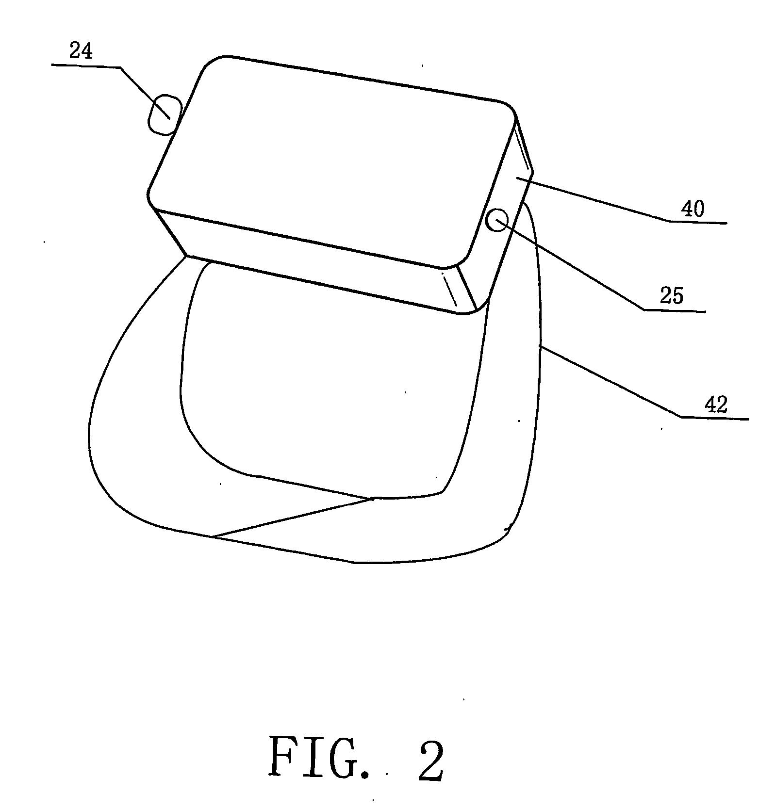
[0024]FIG. 5 shows an exemplary external design of input device 80 according to the second embodiment of the invention. As shown in FIG. 5, input device 80 includes a stem 84 having a recess 86, and a 3D motion detection sensor IC chip 88 mounted on stem 84. The user can simply hold stem 84 at recess 86 with an index finger so as to fix the relative position of input device 80 with respect to the user'...


PUM


Abstract

The present invention provides an input device that gives users more flexibility and convenience by allowing them to move the input device in a three-dimensional (3D) space without requiring any flat surface. According to one embodiment of the invention, an input device is provided. The input device comprises a motion detection sensor that generates (3D) motion data associated with (3D) movement of the input device. The device wirelessly transmits the motion data to a computer to cause the computer to derive a distance and direction of the movement of the input device in a two-dimensional plane based on the motion data. The computer then moves a cursor to a corresponding position based on the distance and direction derived. The input device also generates control signals in response to a user's command to cause the computer to perform a corresponding cursor action, e.g., a double click operation.

Description

BACKGROUND OF THE INVENTION [0001] The invention relates generally to input devices, and more particularly to contactless input devices. [0002] Input devices are used to feed data into computers or handheld devices, etc. Computer mice and trackballs are all examples of input devices. A computer mouse is a widely-used input device that controls the movement of the cursor on a display. A trackball is a mouse lying on its back and is popular for portable computers. At present, most conventional input devices suffer from drawbacks. For example, with a conventional mouse, wired or wireless, a user has to operate it on a flat surface, such as a mouse pad. This limits the choices available to the users. For instance, if a user wants to use it during a presentation or a lecture, he or she would have to go to the place where the mouse is located to use it, or control a wireless mouse on a flat surface. This can cause much inconvenience for the user while standing in the middle of the room, g...

Claims


Application Information

Patent Timeline
Patent Type & Authority Applications(United States)
IPC IPC(8): G09G5/08G06F3/033G06F3/048
CPCG06F3/0346G06F3/04815
Inventor TU, JIAWENSHAO, XIAOLINGFENG, LEI
Owner KONINKLIJKE PHILIPS ELECTRONICS NV
Features
  • Generate Ideas
  • Intellectual Property
  • Life Sciences
  • Materials
  • Tech Scout
  • Unparalleled Data Quality
  • Higher Quality Content
  • 60% Fewer Hallucinations
Learn More