Battery switch for downhole tools

a technology of battery switch and tool, which is applied in the direction of battery disconnect circuit, safety/protection circuit, electrical apparatus, etc., can solve the problems of insufficient recovery of electrical power, inefficient operation of high-temperature batteries, and inability to operate in high-temperature environments. achieve the effect of preventing power loss of batteries

Inactive Publication Date: 2006-06-15
SCHLUMBERGER TECH CORP
View PDF33 Cites 38 Cited by
  • Summary
  • Abstract
  • Description
  • Claims
  • Application Information

AI Technical Summary

Benefits of technology

[0013] In another aspect, the invention relates to a method for preventing power loss in a battery in a downhole tool positioned in a wellbore penetrating a subsurface formation. The method includes measuring a tool temperature and closing at least one switch in a battery circuit when the tool temperature exceeds a selected temperature. The method may also include using a hysteresis mechanism to prevent repeated opening and closing of the at least one switch when the tool temperature is near the selected temperature.

Problems solved by technology

Conventional batteries are generally not well-suited for operation in a high temperature environment.
A high-temperature battery, however, will generally operate inefficiently at lower temperatures.
Moreover, drawing power from a high temperature battery at low temperatures may effectively consume an inordinate amount of electrical power that cannot be recovered.

Method used


Image

  • Battery switch for downhole tools
  • Battery switch for downhole tools
  • Battery switch for downhole tools

Examples


Embodiment Construction

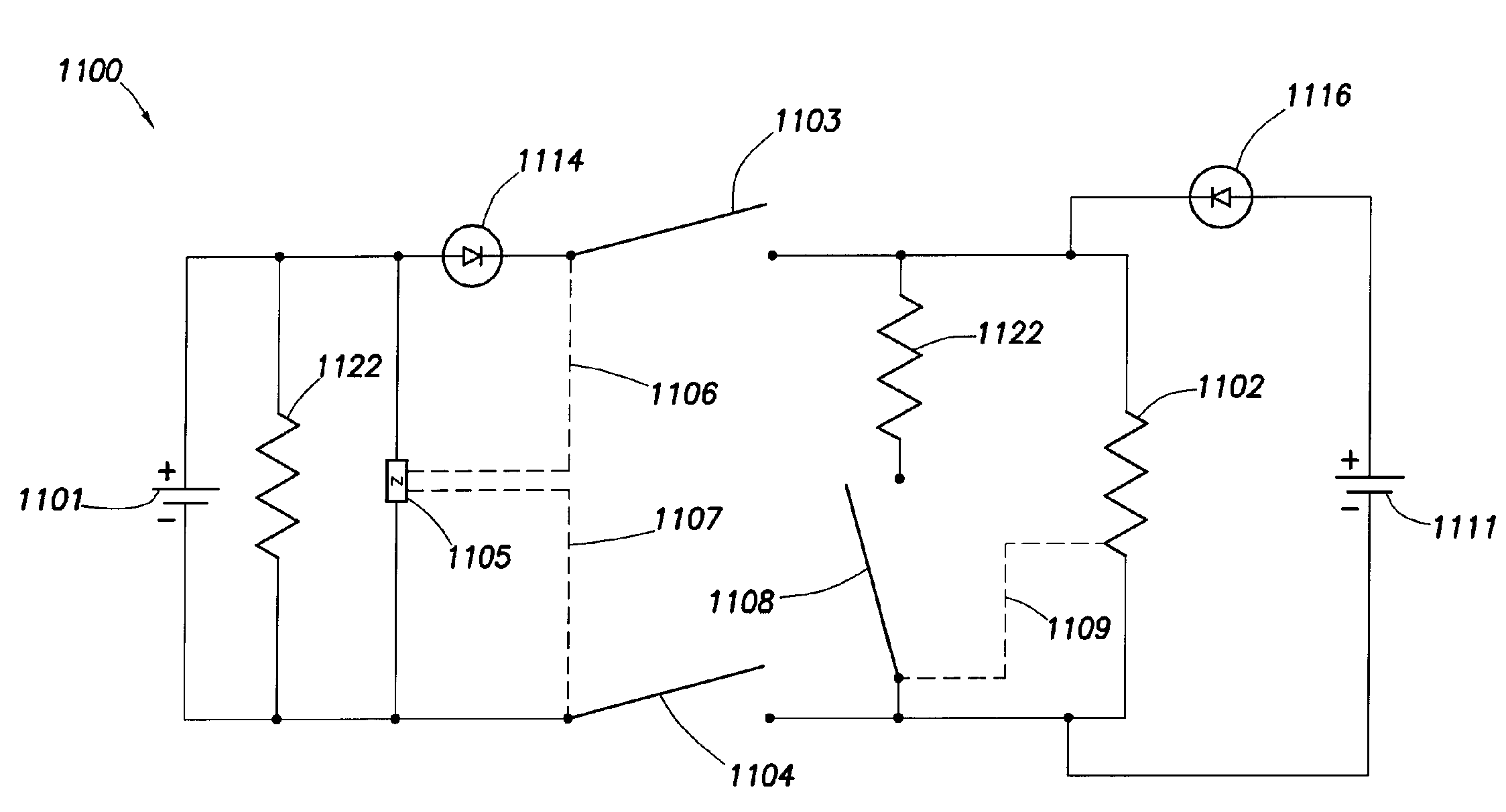
[0029] The present invention relates to downhole tool circuits that include one or more switches to disengage a battery when the tool temperature is not within a desired operating range for the battery. The invention may also relate to various other components that may be useful in such a system.

[0030] The following section includes definitions of specific terms used in this disclosure.

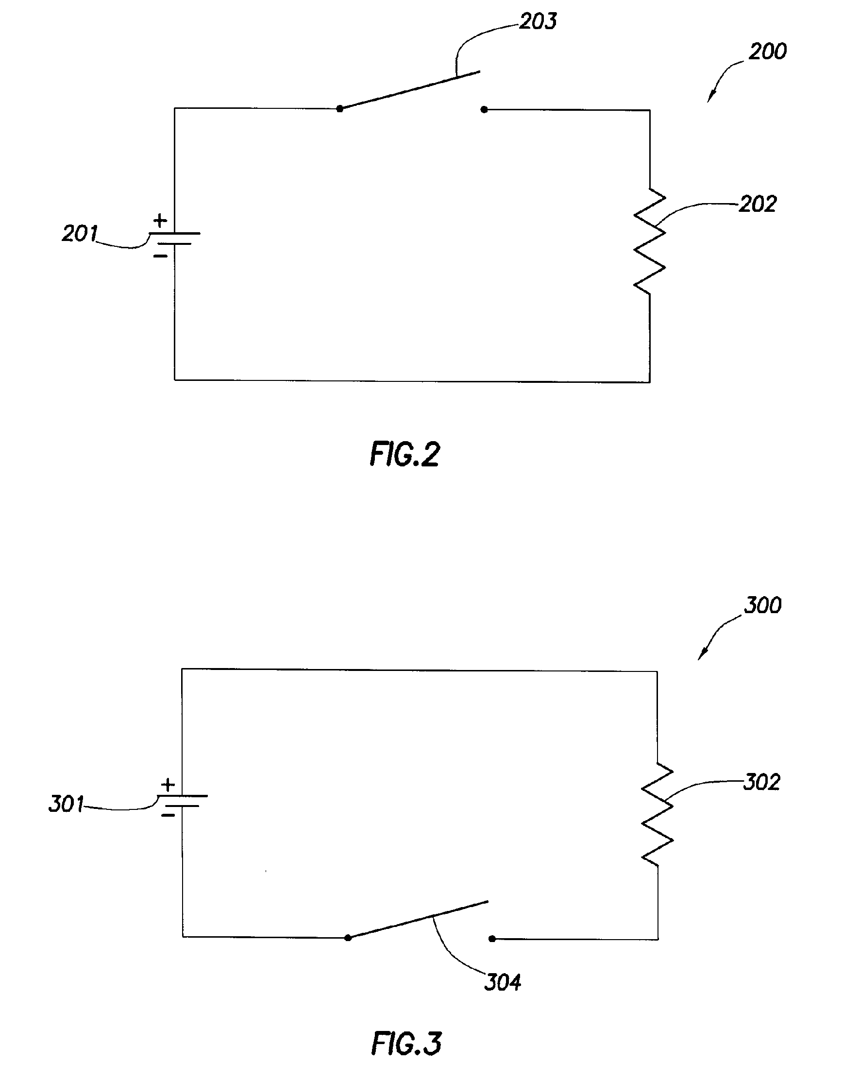
[0031] In this disclosure, components that are “electrically connected” are connected in such a way that electric current may flow between the components. Components that are electrically connected may include additional components that are connected between them. In addition, in some cases, a switch may be electrically connected to various components in a circuit. Even though a switch may be in an open position, which would break the circuit and prevent electrical flow, this does not prevent components from being electrically connected in accordance with the invention. A switch is intended to be cl...


PUM


Abstract

An electrical circuit for a downhole tool may include a battery, a load electrically connected to the battery, and at least one switch electrically connected in series with the battery and to the load. The at least one switch may be configured to close when a tool temperature exceeds a selected temperature.

Description

STATEMENT REGARDING FEDERALLY SPONSORED RESEARCH OR DEVELOPMENT [0001] This invention was made with Government support under Cooperative Agreement No. DE-FC26-03NT41835 awarded by the department of Energy (DOE). The Government has certain rights in this invention.BACKGROUND OF INVENTION [0002] Wells are generally drilled into the ground to recover natural deposits of oil and gas, as well as other desirable materials, that are trapped in geological formations in the Earth's crust. A well is drilled into the ground using a drill bit at the end of a drill string. The drill bit is directed to the targeted geological location from a drilling rig at the Earth's surface. A drilling fluid, called “mud,” is pumped down through the drill string to the drill bit. The mud cools and lubricates the drill bit, and it carries the drill cuttings away from the bottom of the borehole. The mud and the drill cuttings flow to the surface through the annulus between the drill string and the borehole wall....

Claims


Application Information

Patent Timeline
Patent Type & Authority Applications(United States)
IPC IPC(8): H02H5/04
CPCH02J7/0031
Inventor BOLING, BRIAN E.
Owner SCHLUMBERGER TECH CORP
Why Eureka
Try Eureka