Method and system for mobile receiver antenna architecture for European cellular and broadcasting services

a mobile receiver and antenna technology, applied in the field of mobile receivers, can solve the problems of inter-symbol interference in received signals, high bit rate data transmission, and significant challenges in deploying broadcast services to mobile user equipment, and achieve the effect of low noise amplifier

Active Publication Date: 2006-06-15
AVAGO TECH INT SALES PTE LTD
View PDF5 Cites 24 Cited by
  • Summary
  • Abstract
  • Description
  • Claims
  • Application Information

AI Technical Summary

Benefits of technology

[0038] A fourth antenna may be coupled to the first RFIC via a first polyphase filter in a transmit path. The fourth antenna may be coupled to the first RFIC via a second polyphase filter in a receive path. The fourth antenna may be coupled to the input of the second polyphase filter. The output of the first polyphase filter may be coupled to the fourth antenna. A fifth antenna may be coupled to the second RFIC via a first transmit path bandpass filter in a transmit path capable of handling signals within the 1800 MHz band. A sixth antenna may be coupled to the second RFIC via a second bandpass filter in a receive path capable of handling signals within the 900 MHz band. A seventh antenna may be coupled to the second RFIC via a second transmit path bandpass filter in a transmit path capable of handling signals within the 900 MHz band. An eighth antenna may be coupled to the first RFIC via a first polyphase filter and a first amplifier in a transmit path capable of handling signals within the 2100 MHz band. The first amplifier may be a power amplifier. A ninth antenna may be coupled to the first RFIC via a second polyphase filter, a second amplifier and a third polyphase filter in a receive path capable of handling signals within the 2100 MHz band. The second amplifier may be a low noise amplifier. A tenth antenna may be coupled to the second RFIC via a first bandpass filter in a receive path capable of handling signals within the 1800 MHz band.
[0039] These and other advantages, aspects and novel features of the present invention, as well as details of an illustrated embodiment thereof, will be more fully understood from the following description and drawings.

Problems solved by technology

One limitation has been that broadcasting may often require high bit rate data transmission at rates higher than could be supported by existing mobile communications networks.
There are also significant challenges in deploying broadcast services to mobile user equipment.
Another consideration is the Doppler effect in moving user equipment, which may cause inter-symbol interference in received signals.

Method used


Image

  • Method and system for mobile receiver antenna architecture for European cellular and broadcasting services
  • Method and system for mobile receiver antenna architecture for European cellular and broadcasting services
  • Method and system for mobile receiver antenna architecture for European cellular and broadcasting services

Examples


Embodiment Construction

[0056] A method for an antenna architecture that handles European band cellular and broadcast channels may be provided. The method may comprise receiving at a first radio frequency integrated circuit (RFIC) integrated within a mobile terminal, first signals via a first antenna, where the first signals comprise signals within a 2100 MHz band. The method may further comprise receiving at a second RFIC integrated within the mobile terminal, second signals via the first antenna, where the second signals comprise signals within at least one of a 1800 MHz band and a 900 MHz band and receiving at a third RFIC integrated within the mobile terminal, third signals via the first antenna, where the third signals comprise signals within a VHF / UHF broadcast band.

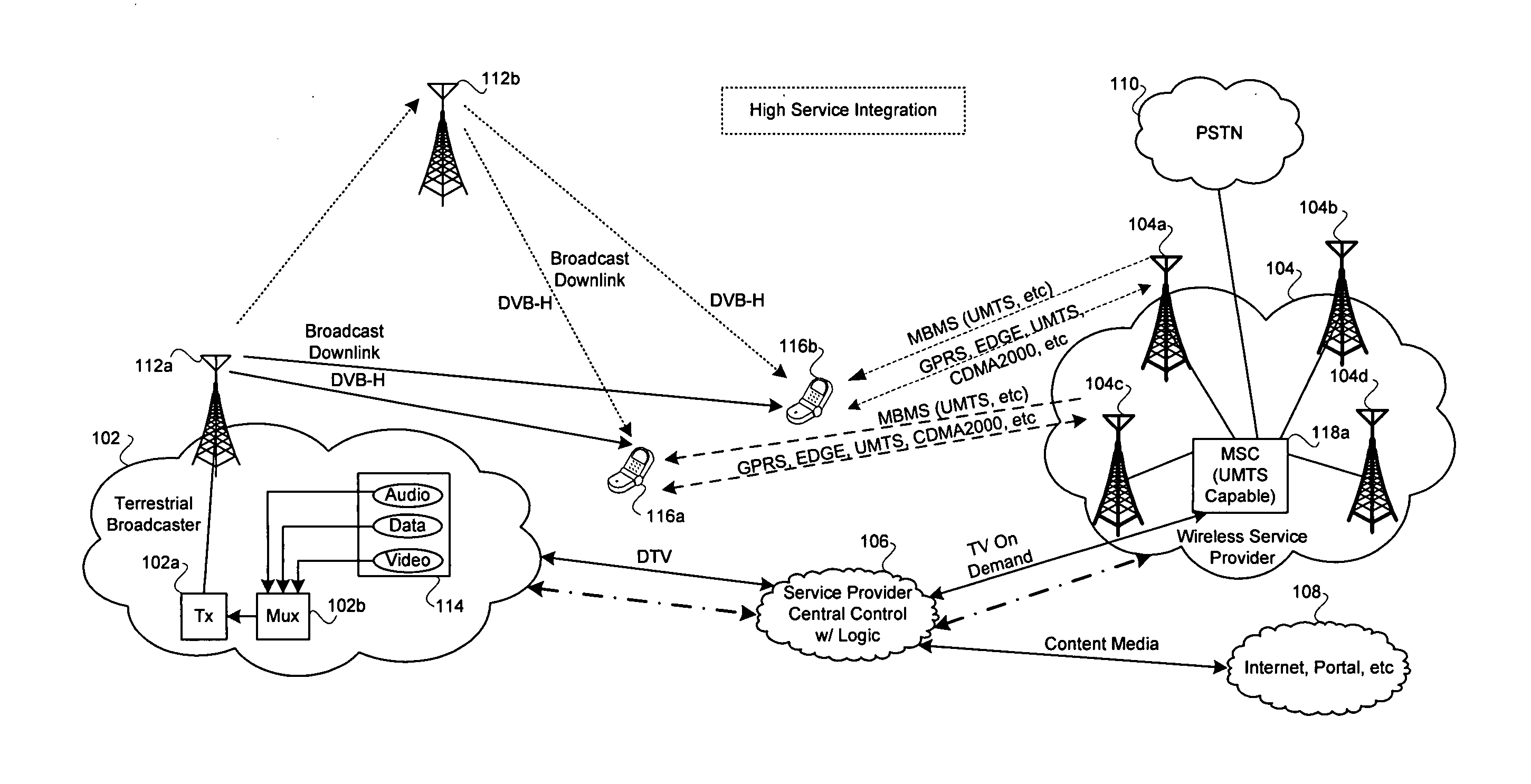
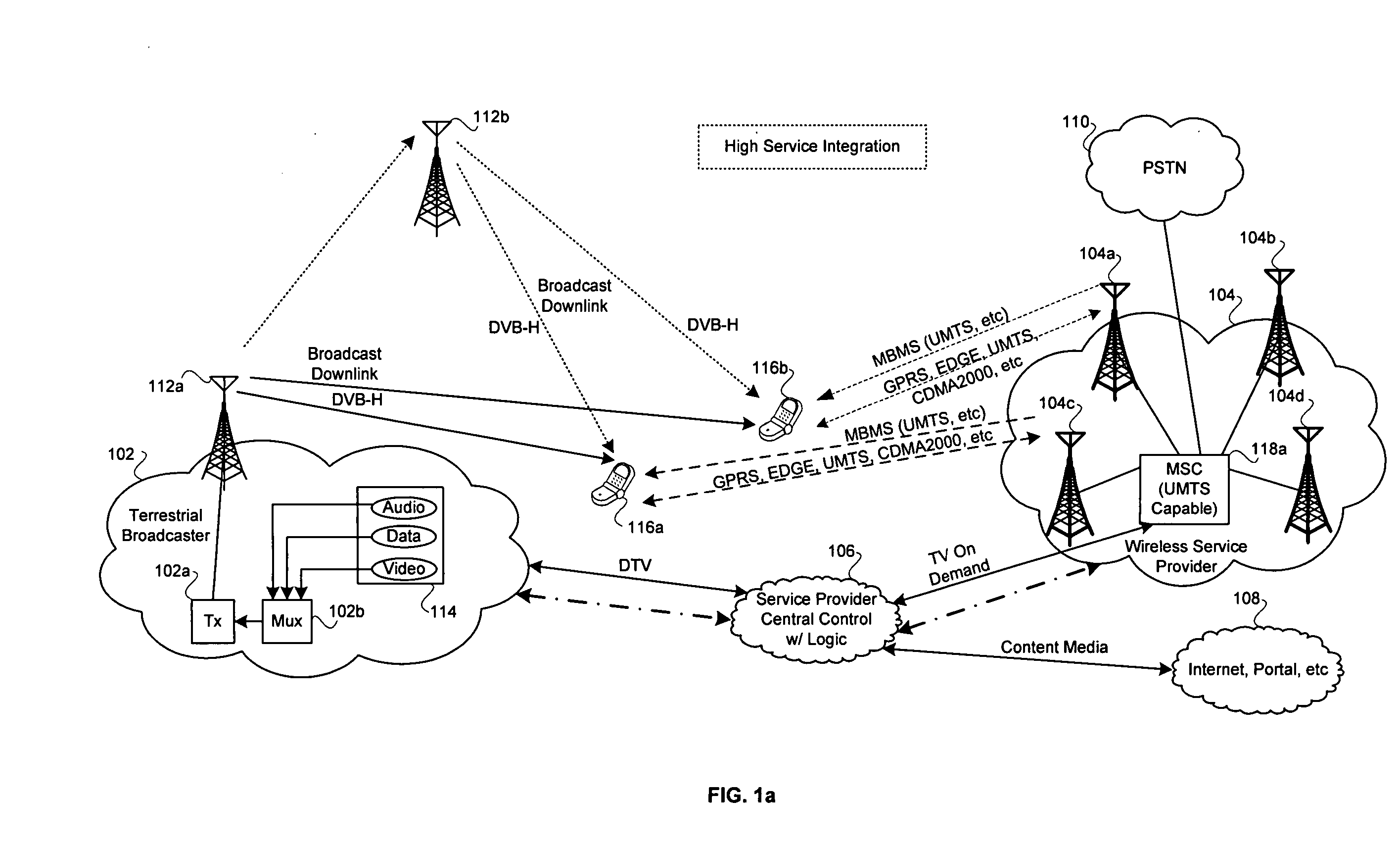
[0057]FIG. 1a is a block diagram of an exemplary system for providing integrated services between a cellular network and a digital video broadcast network, in accordance with an embodiment of the invention. Referring to FIG. 1a, there is...


PUM


Abstract

A method for an antenna architecture that handles European band cellular and broadcast channels may be provided. The method may comprise receiving at a first radio frequency integrated circuit (RFIC) integrated within a mobile terminal, first signals via a first antenna, where the first signals comprise signals within a 2100 MHz band. The method may further comprise receiving at a second RFIC integrated within the mobile terminal, second signals via the first antenna, where the second signals comprise signals within at least one of a 1800 MHz band and a 900 MHz band and receiving at a third RFIC integrated within the mobile terminal, third signals via the first antenna, where the third signals comprise signals within a VHF/UHF broadcast band.

Description

CROSS-REFERENCE TO RELATED APPLICATIONS / INCORPORATION BY REFERENCE [0001] This application makes reference to: [0002] U.S. patent application Ser. No. ______ (Attorney Docket No. 16330US01), filed Dec. 13, 2004; [0003] U.S. patent application Ser. No. ______ (Attorney Docket No. 16331US01), filed Dec. 13, 2004; [0004] U.S. patent application Ser. No. ______ (Attorney Docket No. 16332US01), filed Dec. 13, 2004; [0005] U.S. patent application Ser. No. ______ (Attorney Docket No. 16333US01), filed Dec. 13, 2004; [0006] U.S. patent application Ser. No. ______ (Attorney Docket No. 16334US01), filed Dec. 13, 2004; [0007] U.S. patent application Ser. No. ______ (Attorney Docket No. 16335US01), filed Dec. 13, 2004; [0008] U.S. patent application Ser. No. ______ (Attorney Docket No. 16336US01), filed Dec. 13, 2004; [0009] U.S. patent application Ser. No. ______ (Attorney Docket No. 16337US01), filed Dec. 13, 2004; [0010] U.S. patent application Ser. No. ______ (Attorney Docket No. 16338US01)...

Claims


Application Information

Patent Timeline
Patent Type & Authority Applications(United States)
IPC IPC(8): H04Q7/20
CPCH04B1/406H04B1/48
Inventor VAN ROOYEN, PIETER GERT WESSEL
Owner AVAGO TECH INT SALES PTE LTD
Why Eureka
Try Eureka