Roadway-transportable artificial golf practice green apparatus

a technology for golf practice and equipment, which is applied in the field of equipment for use as golf target practice greens, can solve the problems of impossible or very difficult transportation, and achieve the effect of facilitating the temporary reduction of the effective width of the golf practice and reducing the width thereo

Inactive Publication Date: 2006-06-15
COX ALVIN E
View PDF21 Cites 1 Cited by
  • Summary
  • Abstract
  • Description
  • Claims
  • Application Information

AI Technical Summary

Benefits of technology

[0010] The present invention relates to a transportable artificial golf practice green having means for reducing the width thereof to allow for the device to be legally transported over a roadway. Several embodiments of the present invention are disclosed herein that facilitate the temporary reduction of the effective width of a golf practice green to within dimensions prescribed by applicable laws for transportation over highways. Such an apparatus allows for a driving range operator to transport one practice green between two different ranges, or between a driving range and the location of a special event or competition, etc. Such transportation has been heretofore impossible or very difficult given the typical size of golf practice greens, often requiring the greens to be significantly disassembled, transported in pieces, and reassembled at the new location.
[0012] In a first embodiment of the instant invention, the generally circular or oval practice green has three panels comprising a center panel and two side panels attached to the center panel with hinges or other means which permit the side panels to rotate with respect to the center panel which remains in a fixed position. In the first configuration, the panels are extended such that the upper surfaces of the panels form a planar coextensive target surface, generally positioned substantially horizontally for use as a practice green. In the second configuration, the side panels are folded at the hinges to a position above the center panel, thereby reducing the effective width of the green, allowing it to be quickly positioned on a vehicle for transportation.

Problems solved by technology

Such transportation has been heretofore impossible or very difficult given the typical size of golf practice greens, often requiring the greens to be significantly disassembled, transported in pieces, and reassembled at the new location.

Method used


Image

  • Roadway-transportable artificial golf practice green apparatus
  • Roadway-transportable artificial golf practice green apparatus
  • Roadway-transportable artificial golf practice green apparatus

Examples


first embodiment

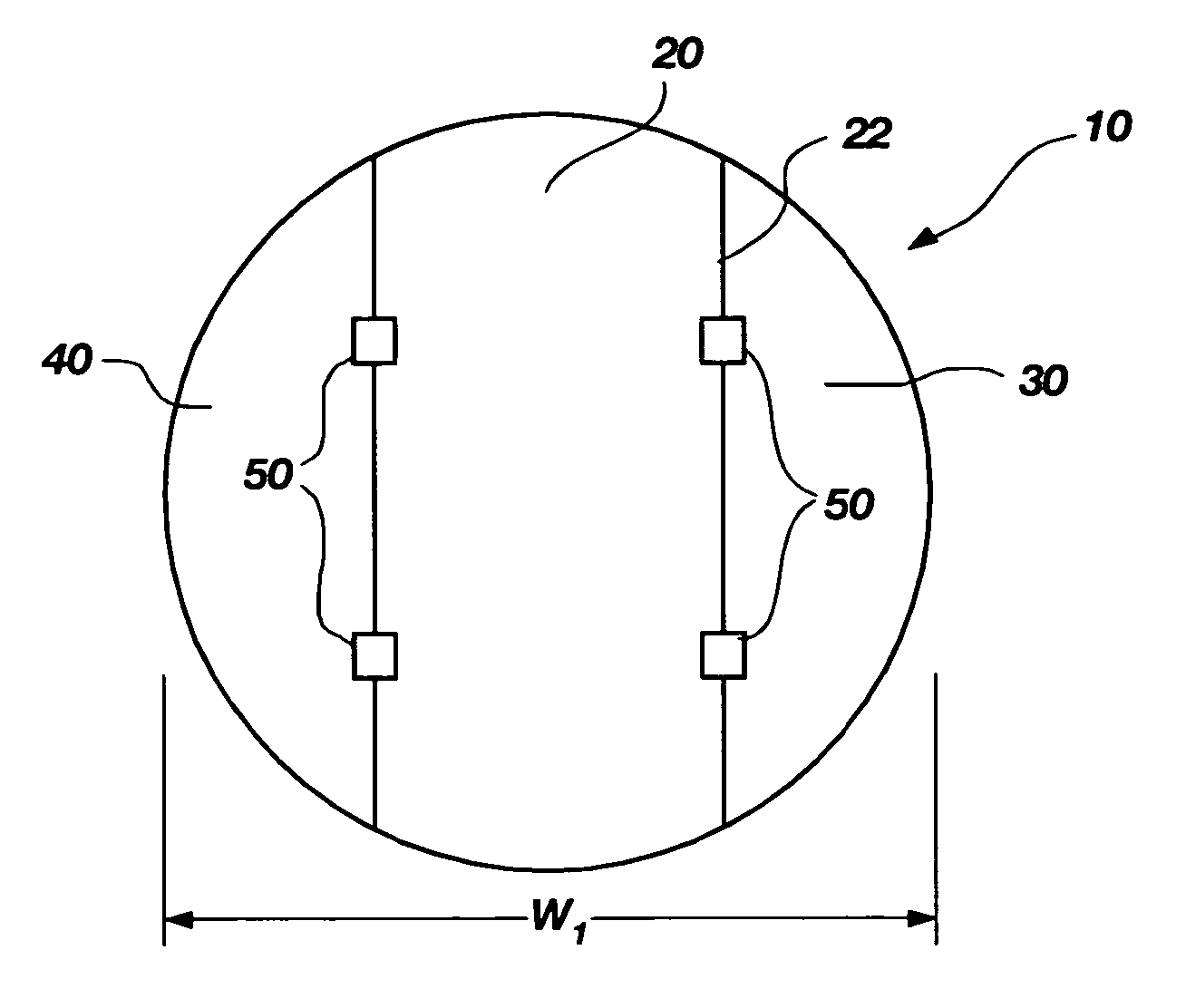
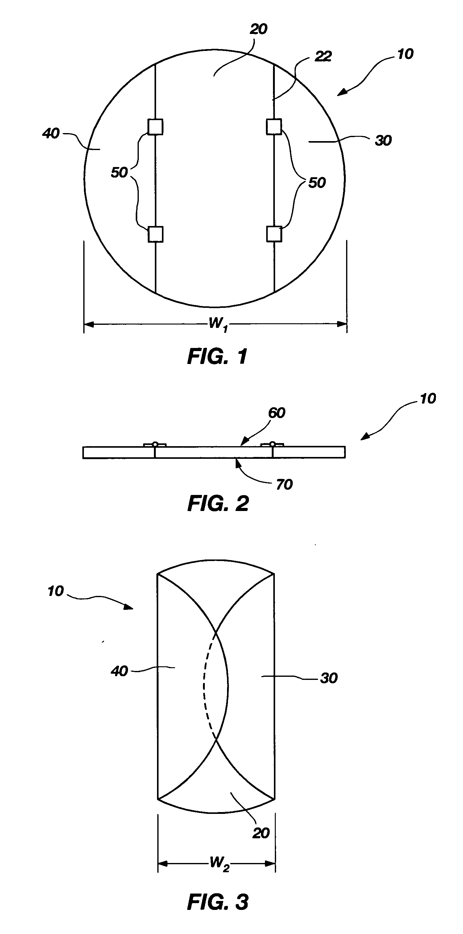
[0031]FIG. 1 is a plan view of the upper surface of a golf practice green apparatus according to the present invention. The practice green comprises three panels, a center panel 20, a side folding panel 30, and an additional side folding panel 40. An edge of center panel 20 abuts an edge of side folding panel 30 at common joint 22. Hinges 50 are placed on the top surface 60 of panels 20 and 30 and fasten them together across common joint 22. Likewise, an edge of center panel 20 abuts an edge of side folding panel 40 at common joint 24. Hinges 50 also fasten panels 20 and 40 together across common joint 24. The hinges may be positioned on the lower surface of the panels or recessed into the panel edges to be within the joint between adjacent panels. Recessed or bottom placed hinges may require the joints 22 and 24 to be more open and / or for the edges of the panels to be curved to accommodate the upward folding of a side panel with respect to the center panel. FIG. 2 is an end (elevat...

fourth embodiment

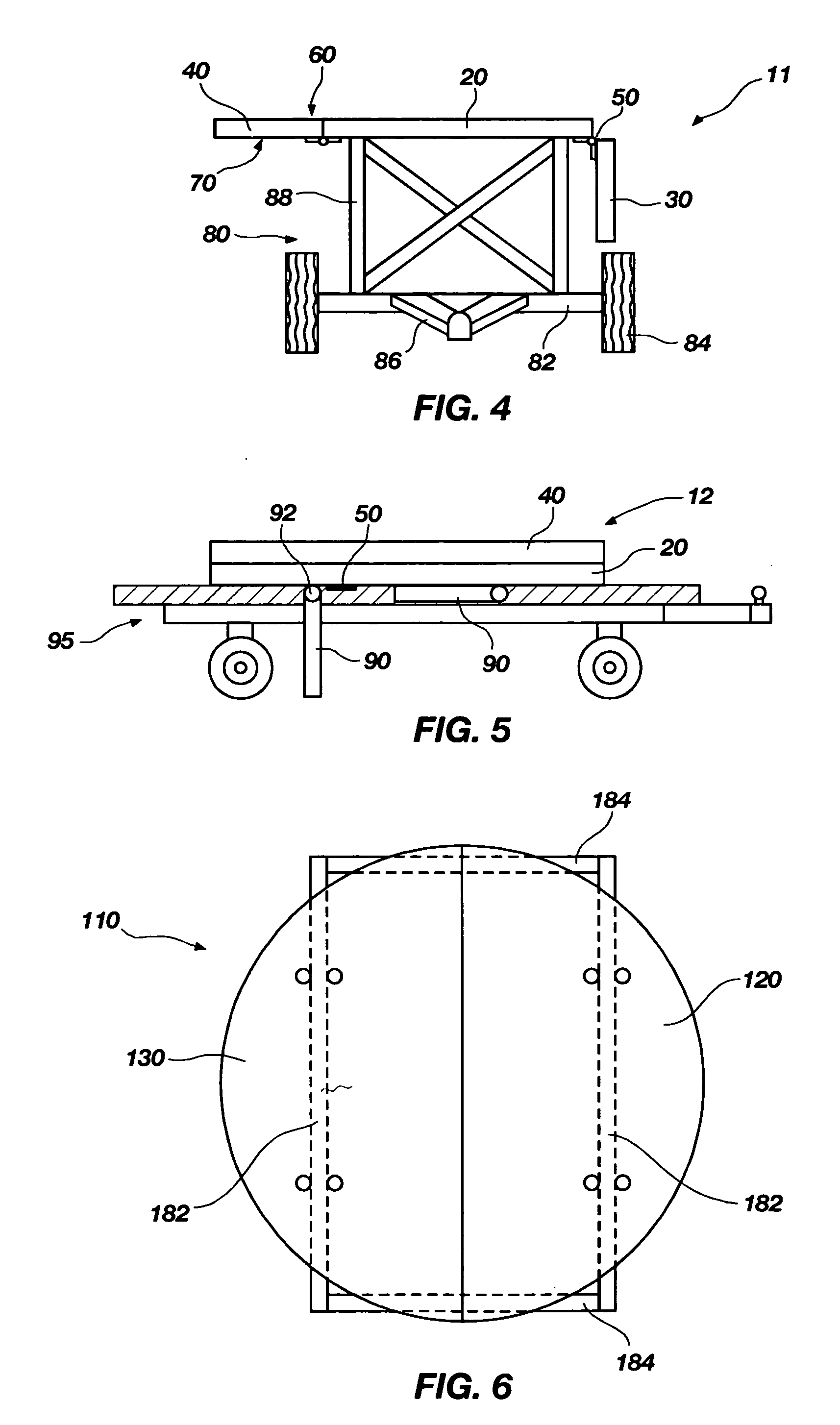
[0038]FIGS. 6, 7 and 8 show a golf practice green apparatus 110 according to the present invention. FIG. 1 is a top plan view of apparatus 110 in a first configuration, while FIGS. 7 and 8 are end views of the apparatus in the first configuration and a second configuration, respectively. The practice green apparatus comprises a first panel 120 and a second panel 130. The apparatus further comprises a support frame structure 180, which comprises a horizontal base member 184 connected to vertical members 186, which are further connected to horizontal support members 182. Panels 120 and 130 are connected to horizontal support members 182 by U-bolts 188, such that the panels are free to rotate about the horizontal support members.

[0039] In the first configuration, panels 120 and 130 extend horizontally such that the top surface 160 of the panels forms a co-planar and continuous surface as shown in FIG. 7. If it is desired to move the apparatus to a different location that requires trans...

fifth embodiment

[0040]FIGS. 9 and 10 illustrate a golf practice green apparatus 210 according to the present invention. The apparatus comprises a rigid tubular U-shaped frame member 282. A canvas or other suitable fabric panel 220 is fastened to, and extends across the area enclosed by, U-shaped frame member 282. The apparatus further comprises an additional rigid generally tubular U-shaped frame member 284 attached to an additional canvas panel 230. As is seen in the cross-sectional view of FIG. 11, taken along line 11-11 of FIG. 10, generally tubular frame member 284 is larger in cross-section than tubular frame member 282. The inner open diameter of tubular frame member 284 is slightly larger than the outer diameter of tubular frame member 282 so that tubular frame member 284 may slide telescopically over tubular frame member 282. Panel 230 is attached to the top surface of tubular frame member 284, while panel 220 is attached to the inside surface of tubular frame member 282. A slot 290 is form...


PUM


Abstract

A golf practice green apparatus is provided which is capable of transforming between multiple configurations. A first configuration is best suited for actual use as a target green on a golf driving range or the like. In a second configuration the effective width or other dimension of the apparatus is significantly reduced to allow for practical and legal transportation of the golf practice green apparatus over a roadway.

Description

CROSS-REFERENCE TO RELATED APPLICATION [0001] This application is a divisional of application Ser. No. 10 / 750,412, filed Dec. 30, 2003, pending.BACKGROUND OF THE INVENTION [0002] 1. Field of the Invention [0003] The present invention relates to apparatus for use as golf target practice greens. Such artificial greens are often used at golf driving ranges or special event competitions. In particular, the present invention relates to a golf practice green which can attain more than one configuration. One configuration will be for use as a target green and another configuration is better suited for highway transportation or to facilitate storage. [0004] 2. State of the Art [0005] Golf practice greens are commonly used on golf course driving ranges to aid golfers in improving their accuracy in hitting golf balls to a desired target, such as the golf hole or pin. Artificial practice greens are often preferable over a natural green (a green and hole placed in the grass itself as is found o...

Claims


Application Information

Patent Timeline
Patent Type & Authority Applications(United States)
IPC IPC(8): A63B69/36A63B67/02A63B57/00
CPCA63B69/3661A63B69/3694
Inventor COX, ALVIN E.
Owner COX ALVIN E
Why Eureka
Try Eureka