Intravascular implants and methods of using the same

Inactive Publication Date: 2006-06-15
ENDOLOGIX LLC
View PDF55 Cites 53 Cited by
  • Summary
  • Abstract
  • Description
  • Claims
  • Application Information

AI Technical Summary

Benefits of technology

[0013] Yet another embodiment of the intravascular implant has a seal, a connector and an anchor. The seal is configured to attach to a second implant. The connector has a first end and a second end and may be flexible. The first end is attached to the seal, and the second e

Problems solved by technology

The stop can be a mec

Method used


Image

  • Intravascular implants and methods of using the same
  • Intravascular implants and methods of using the same
  • Intravascular implants and methods of using the same

Examples


Embodiment Construction

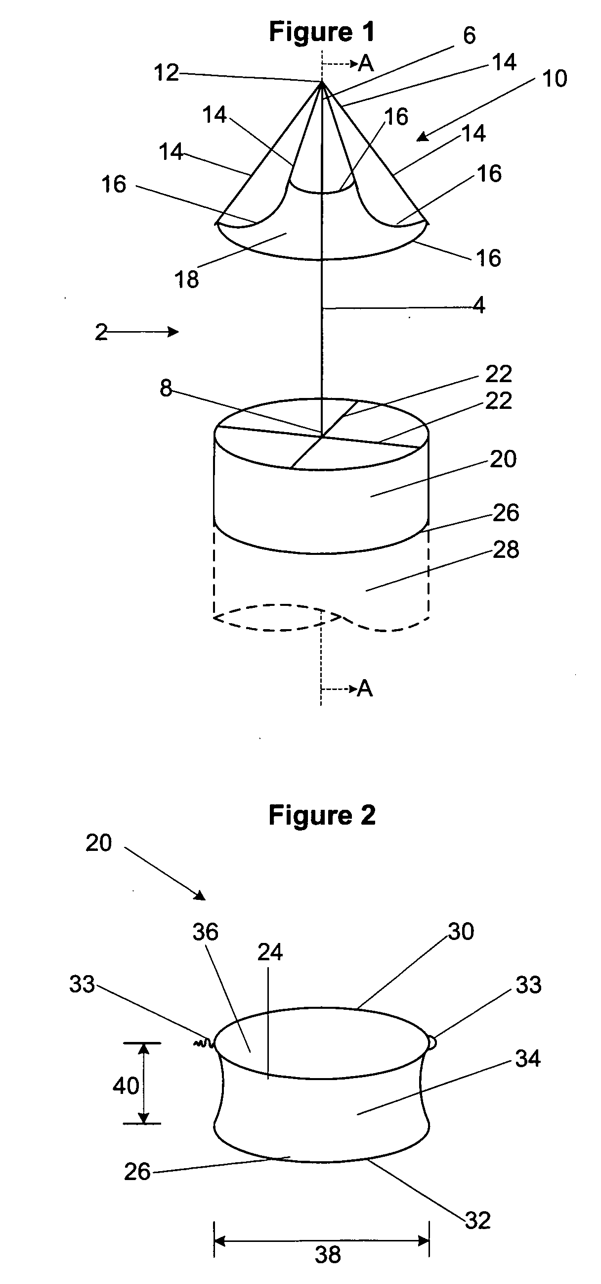
[0041]FIG. 1 illustrates an embodiment of an intravascular implant 2. The implant 2 can have a connector 4 having a first end 6 and a second end 8. The first end 6 can be attached to an anchor 10. The anchor 10 can have a central tip 12. The central tip 12 can be attached to the first end 6. The anchor 10 can also have multiple tines or arms 14 extending radially from the central tip 12, such as in an uncovered umbrella structure. The central tip 12 can be rotatably or flexibly attached to the arms 14. Leaves 16 can be attached at two ends to adjacent arms 14. A flow-through area 18 can be an open port defined by any leaf 16 and the arms 14 to which that leaf 16 attaches.

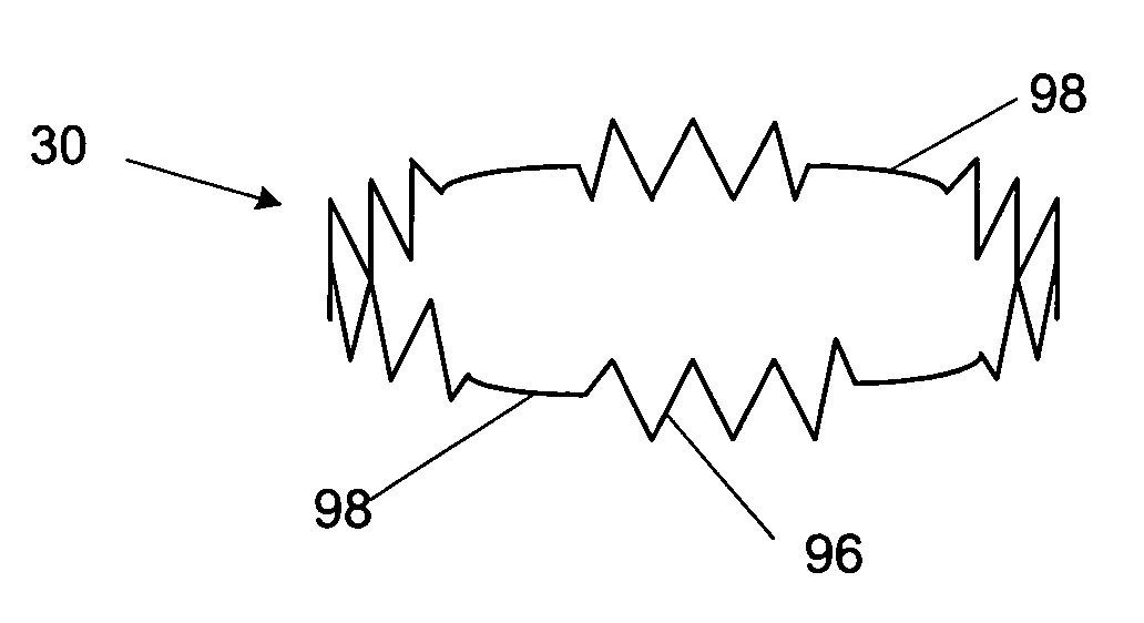
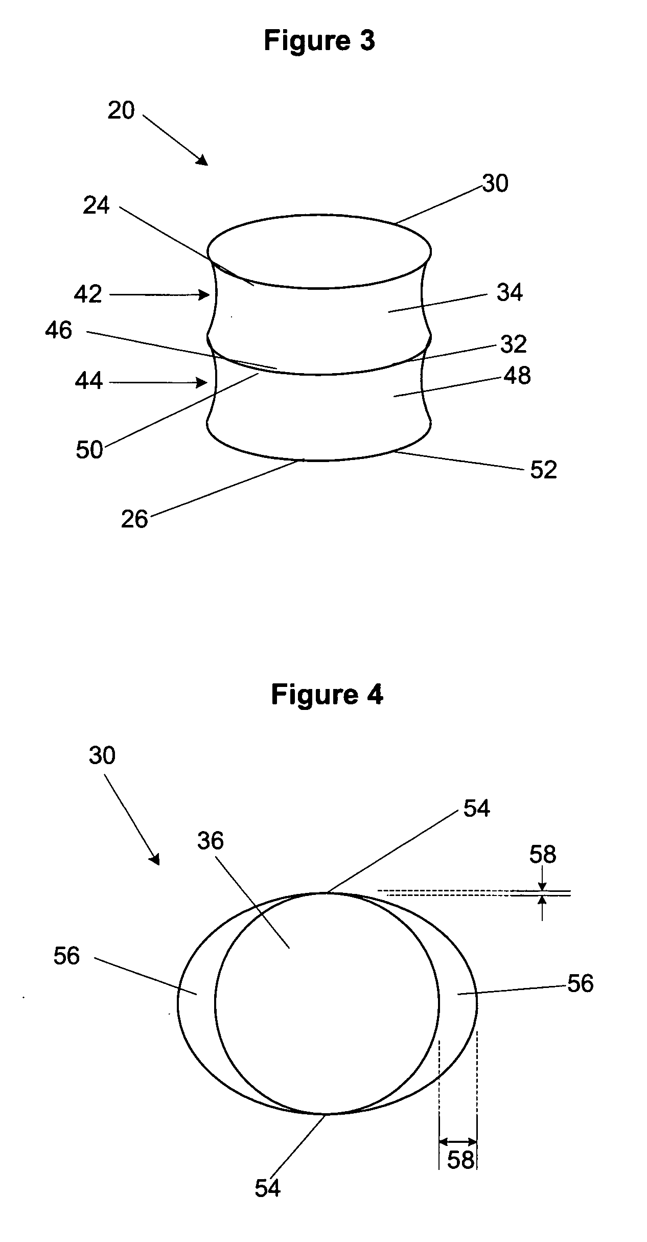
[0042] The second end 8 can be attached to a seal 20. The second end 8 can attach to the seal 20 through an attachment device 22, for example struts. The attachment device 22 can be integral with the second end 8, integral with the seal 20, or an independent part. Attachment devices 22 can also be used to attach th...


PUM


Abstract

An intravascular implant and methods of using the implant within the vasculature of the body, for example near a vascular aneurysm, are disclosed. The method of attaching a second implant, such as a vascular graft, to the intravascular implant is also disclosed. The implant can be made from an anchor, a connector and a seal.

Description

CROSS-REFERENCE TO RELATED APPLICATIONS [0001] This application is a continuation of U.S. patent application Ser. No. 10 / 778,870 filed Feb. 12, 2004, which claims the benefit of U.S. Provisional Application No. 60 / 447,056, filed Feb. 12, 2003, the contents of which are incorporated herein by reference in their entirety.BACKGROUND OF THE INVENTION [0002] 1. Field of the Invention [0003] The present invention relates generally to an intravascular implant and methods of using the implant within the vasculature of the body, particularly adjacent to vascular aneurysms. The present invention also relates to the attachment of a second implant, such as a vascular graft, to the intravascular implant. [0004] 2. Description of the Related Art [0005] An aneurysm is an abnormal dilatation of a biological vessel. Aneurysms can alter flow through the affected vessel and often decrease the strength of the vessel wall, thereby increasing the vessel's risk of rupturing at the point of dilation or wea...

Claims


Application Information

Patent Timeline
IPC IPC(8): A61F2/06
CPCA61F2/07A61F2002/065A61F2/88A61F2/89A61F2220/0075A61F2002/068A61F2002/075A61F2250/0069
Inventor FOGARTY, THOMAS J.DREWS, MICHAEL J.HOLMGREN, NEILMODESITT, D. BRUCE
Owner ENDOLOGIX LLC
Why Eureka
Try Eureka