

Quick release paint roller assembly
a quick release, paint roller technology, applied in the field of roller assembly, can solve the problems of the use life of the roller cover is often quite limited, and the paint getting on the hands and clothes of the person removing the roller cover
- Summary
- Abstract
- Description
- Claims
- Application Information
AI Technical Summary
Benefits of technology
Problems solved by technology
Method used
Image

Examples
Embodiment Construction
[0021] The invention will now be described in the following detailed description with reference to the drawings, wherein preferred embodiments are described in detail to enable practice of the invention. Although the invention is described with reference to these specific preferred embodiments, it will be understood that the invention is not limited to these preferred embodiments. But to the contrary, the invention includes numerous alternatives, modifications and equivalents as will become apparent from consideration of the following detailed description.
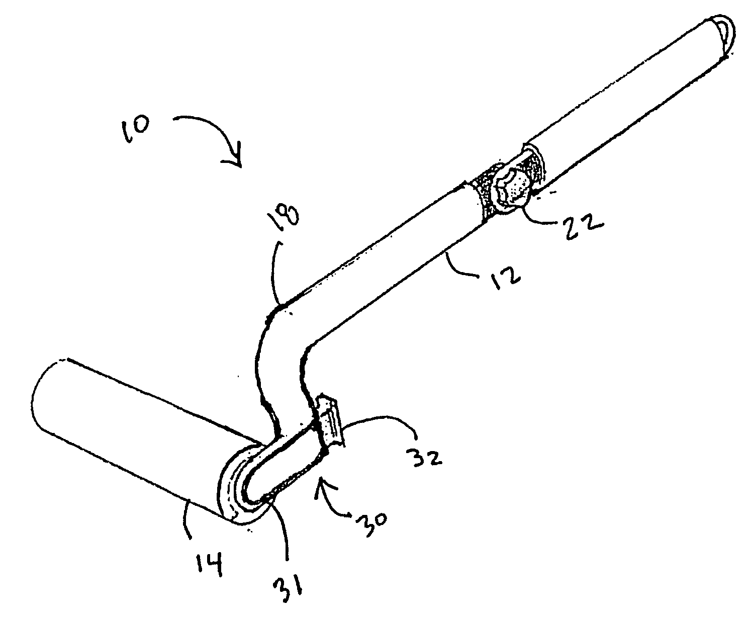
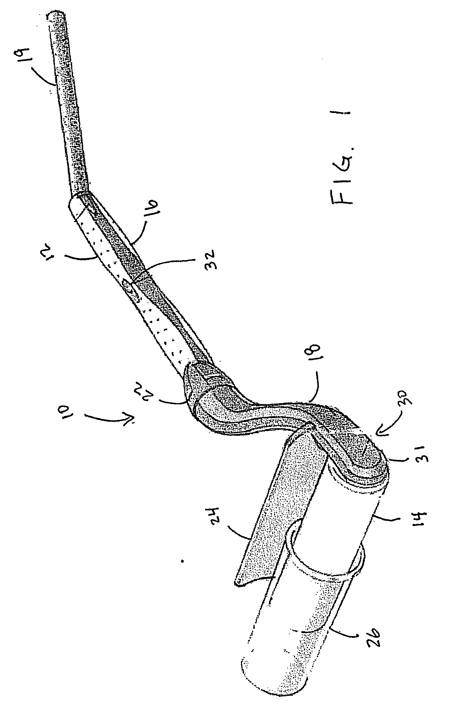
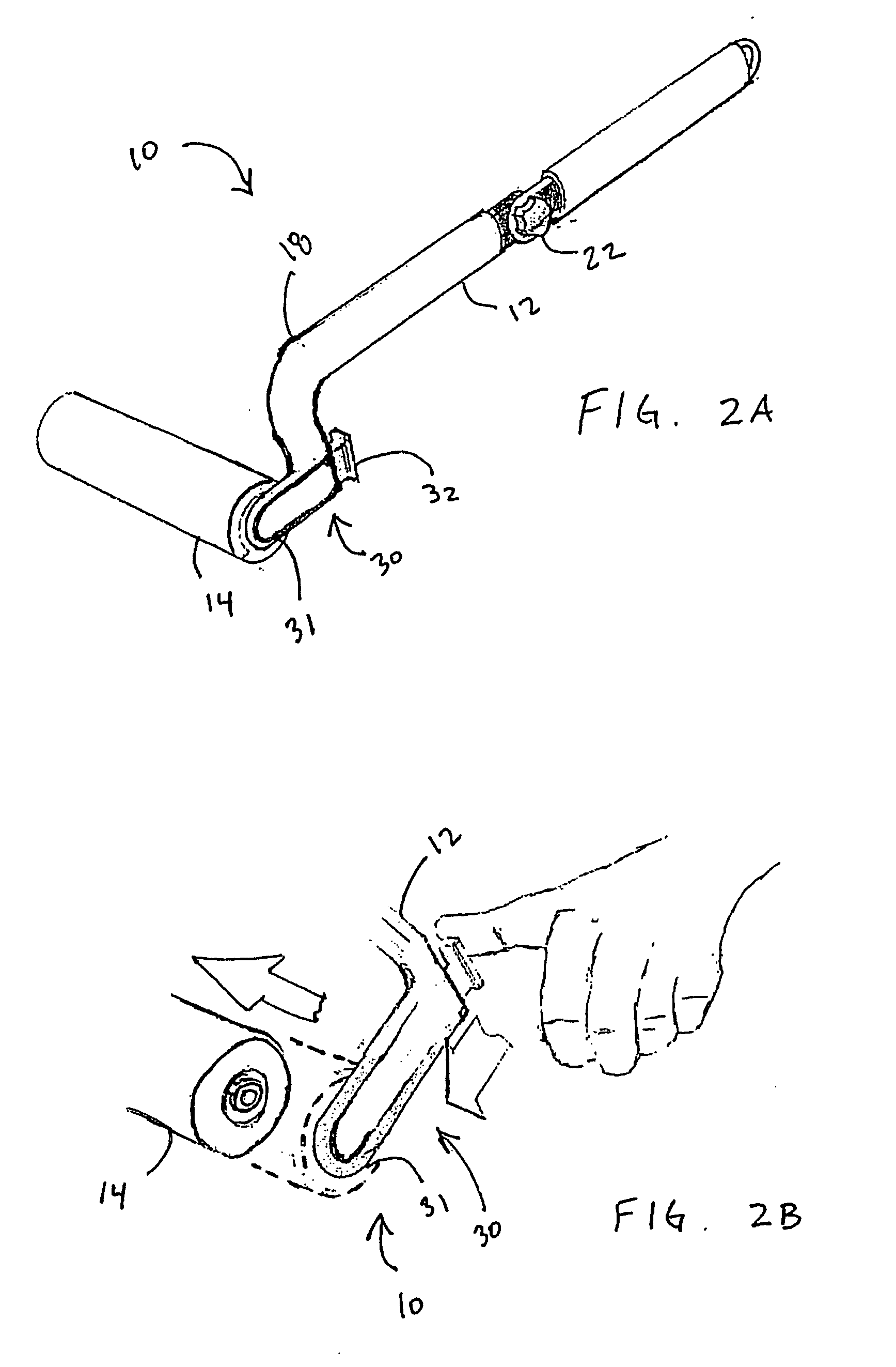
[0022] Referring now to FIGS. 1 and 2, the invention is directed to a roller tool assembly generally designated by the reference number 10 for use in applying paint or other product to a work surface. The paint roller 10 includes a handle assembly generally designated by the reference numeral 12 and a roller cover 14 rotatably coupled thereto. The handle assembly 12 includes a hand grip 16 useful for gripping the paint roller 10 a...
PUM
 Abstract
Description
Claims
Application Information