
Solar panel with optical films

a solar panel and optical film technology, applied in the field of solar cells and electronic devices, can solve the problems of short battery life, inability to meet additional energy sources, and inability to meet the needs of power consumption and demand,

Inactive Publication Date: 2006-06-22
MOTOROLA INC
View PDF9 Cites 55 Cited by
  • Summary
  • Abstract
  • Description
  • Claims
  • Application Information

AI Technical Summary

Problems solved by technology

As demand for newer features and functions increases, power consumption demands continue to increase from an energy source, typically a rechargeable battery, found in many portable wireless communication devices such as cell phones.
A short battery life can be detrimental to the commercial viability of a product such as a wireless communication device.
Unfortunately, advancements in energy source technology have not been able to keep pace with additional new features that continue to additionally drain the energy source on wireless communication devices.
This is an ongoing problem.
Unfortunately, many electronic devices, including for example cellular telephones and other wireless communications devices have had both a higher power demand and an often-limited available surface area for locating a solar cell on the outer surface of the device.
As a result, solar cells have not been viewed as a satisfactory supplemental or alternative power source for such devices.
While there has been a constant need in improving power performance of a portable electronic device, such as a wireless communication device, and while solar power solutions have been promising, one of the issues with solar panel technology is its very unappealing appearance, being mostly very dark with shining electrodes on its surface.
This generates a great mismatch in the visual appearance between the solar panel and the exterior of the hosting electronic device.
This problem is particularly severe with consumer products to which users associate a high premium value with respect to product aesthetics and particularly to a product's external cosmetic appearance.

Method used


Image

  • Solar panel with optical films
  • Solar panel with optical films
  • Solar panel with optical films

Examples


Embodiment Construction

[0018] As required, detailed embodiments of the present invention are disclosed herein; however, it is to be understood that the disclosed embodiments are merely exemplary of the invention, which can be embodied in various forms. Therefore, specific structural and functional details disclosed herein are not to be interpreted as limiting, but merely as a basis for the claims and as a representative basis for teaching one skilled in the art to variously employ the present invention in virtually any appropriately detailed structure. Further, the terms and phrases used herein are not intended to be limiting; but rather, to provide an understandable description of the invention.

[0019] The terms “a” or “an”, as used herein, are defined as one or more than one. The term plurality, as used herein, is defined as two or more than two. The term another, as used herein, is defined as at least a second or more. The terms including and / or having, as used herein, are defined as comprising (i.e., ...


PUM


Abstract

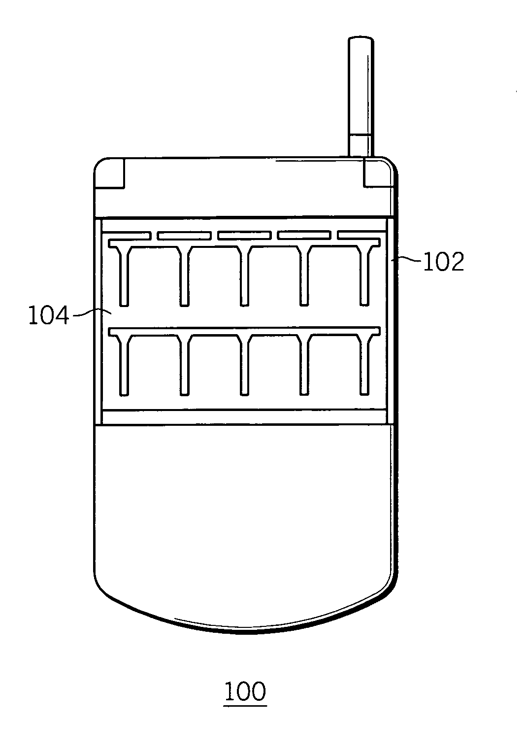
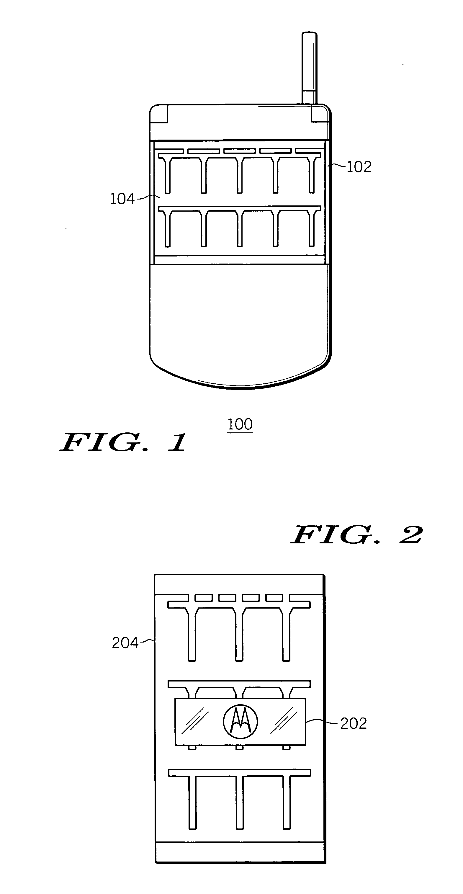
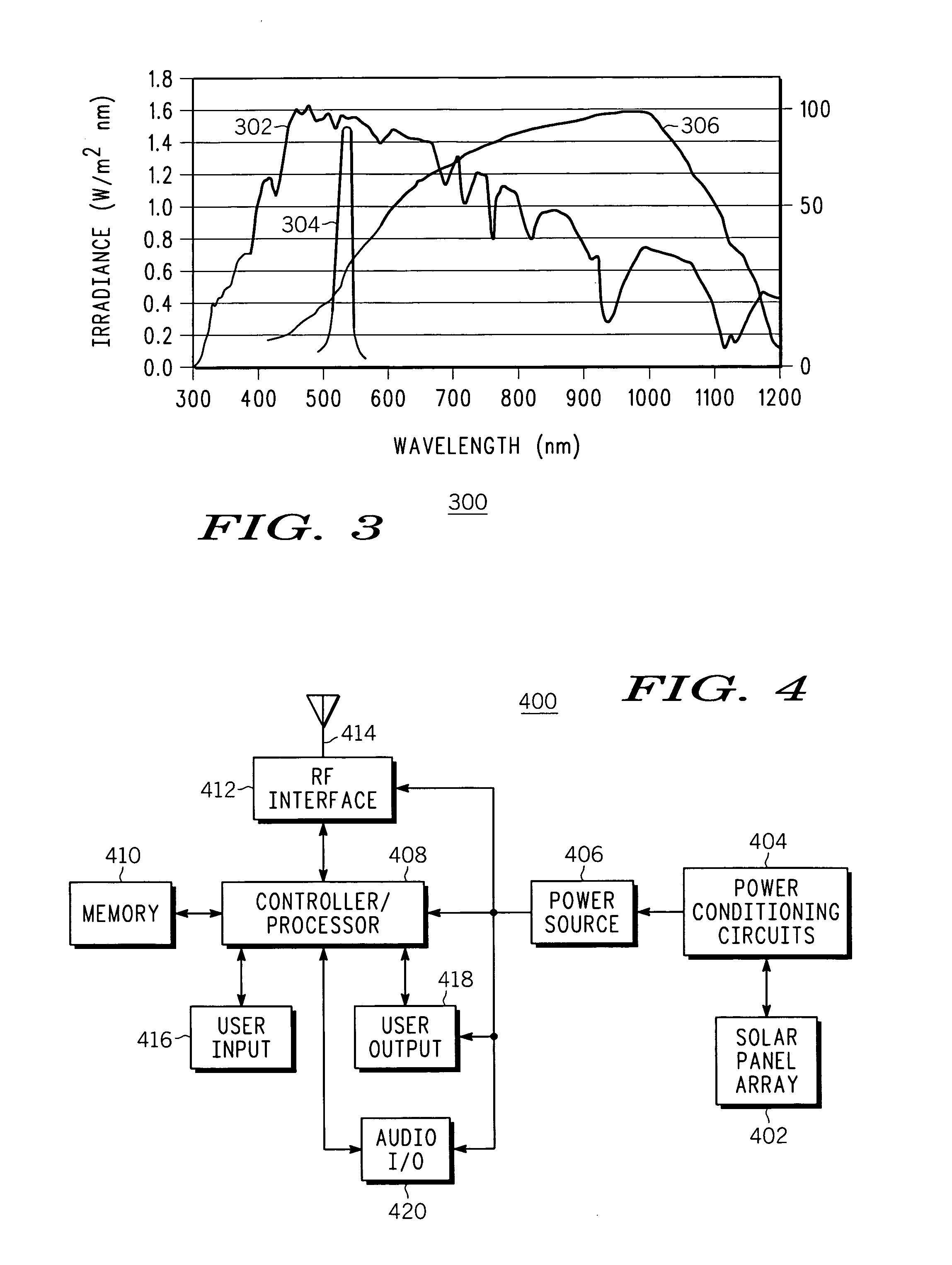
A solar panel mounting arrangement, and electronic device, and a wireless device, includes a solar panel (204); and a wavelength selectively reflective optical film (202) being disposed in front of the solar panel for the optical film to substantially reflect a pre-selected band (304) of solar irradiation frequencies (302) in the visible light range and incident on a front surface of the optical film (202) while allowing solar irradiation frequencies (302) outside of the pre-selected band (304) to substantially pass through the optical film (202) and irradiate the solar panel (204). The optical film (202) can include at least one of an iconic pattern, a company logo, and a photo, that is visible from the front of the optical film (202). The optical film (202) can include holographic film. The optical film can include a multi-layer film.

Description

FIELD OF THE INVENTION [0001] The present invention generally relates to the field of solar cells and electronic devices that utilize solar cells, and more particularly relates to solar panels and optical films utilized by electronic devices such as wireless communication devices and cellular phones. BACKGROUND OF THE INVENTION [0002] Electronic devices, such as wireless communication devices including cell phones, portable two-way radios, wireless communicators, and the like, are being used by a large range of users for a wide variety of applications. As demand for newer features and functions increases, power consumption demands continue to increase from an energy source, typically a rechargeable battery, found in many portable wireless communication devices such as cell phones. The life of a battery is very important to users of portable electronic devices, including users of wireless communication devices. A short battery life can be detrimental to the commercial viability of a ...

Claims


Application Information

Patent Timeline
Patent Type & Authority Applications(United States)
IPC IPC(8): H01L25/00
CPCH01L31/02167Y02E10/50H01L31/048H01L31/04
Inventor LI, ZILIANSON, DENNIS G.
Owner MOTOROLA INC
Learn More