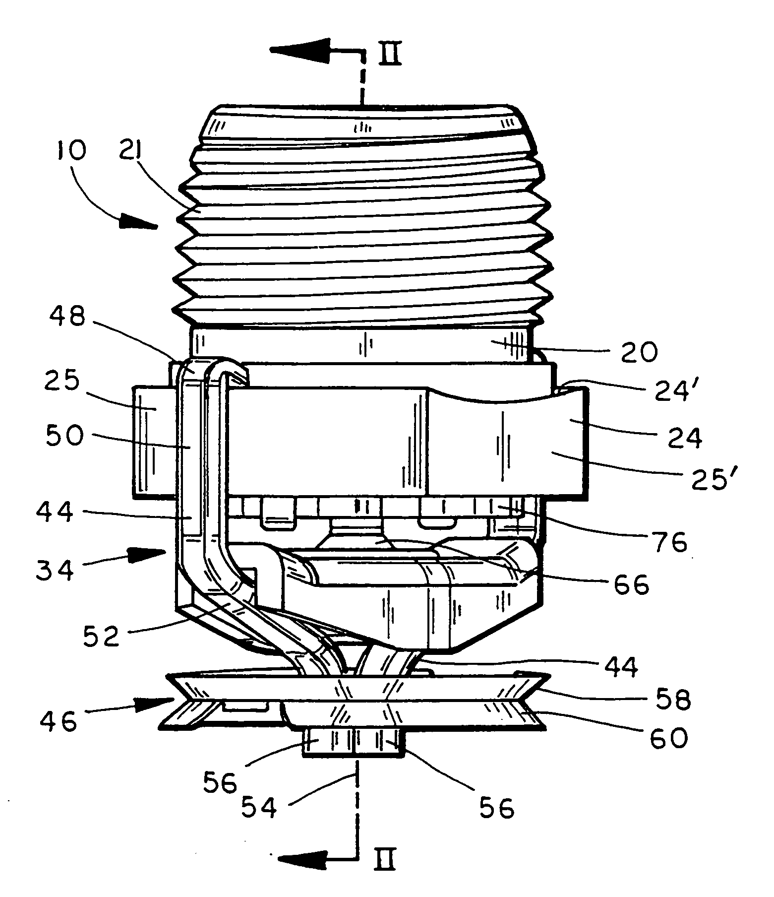
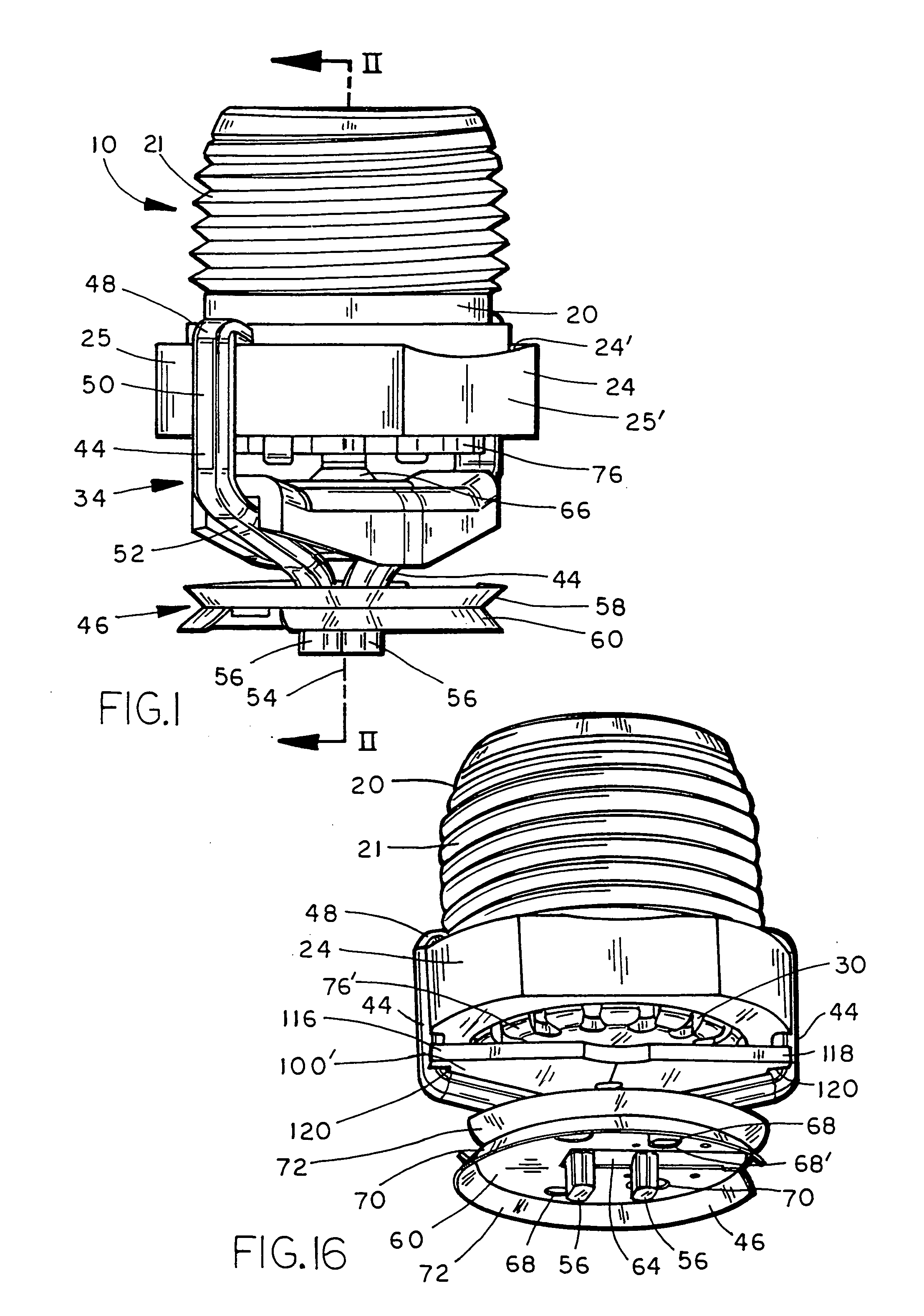
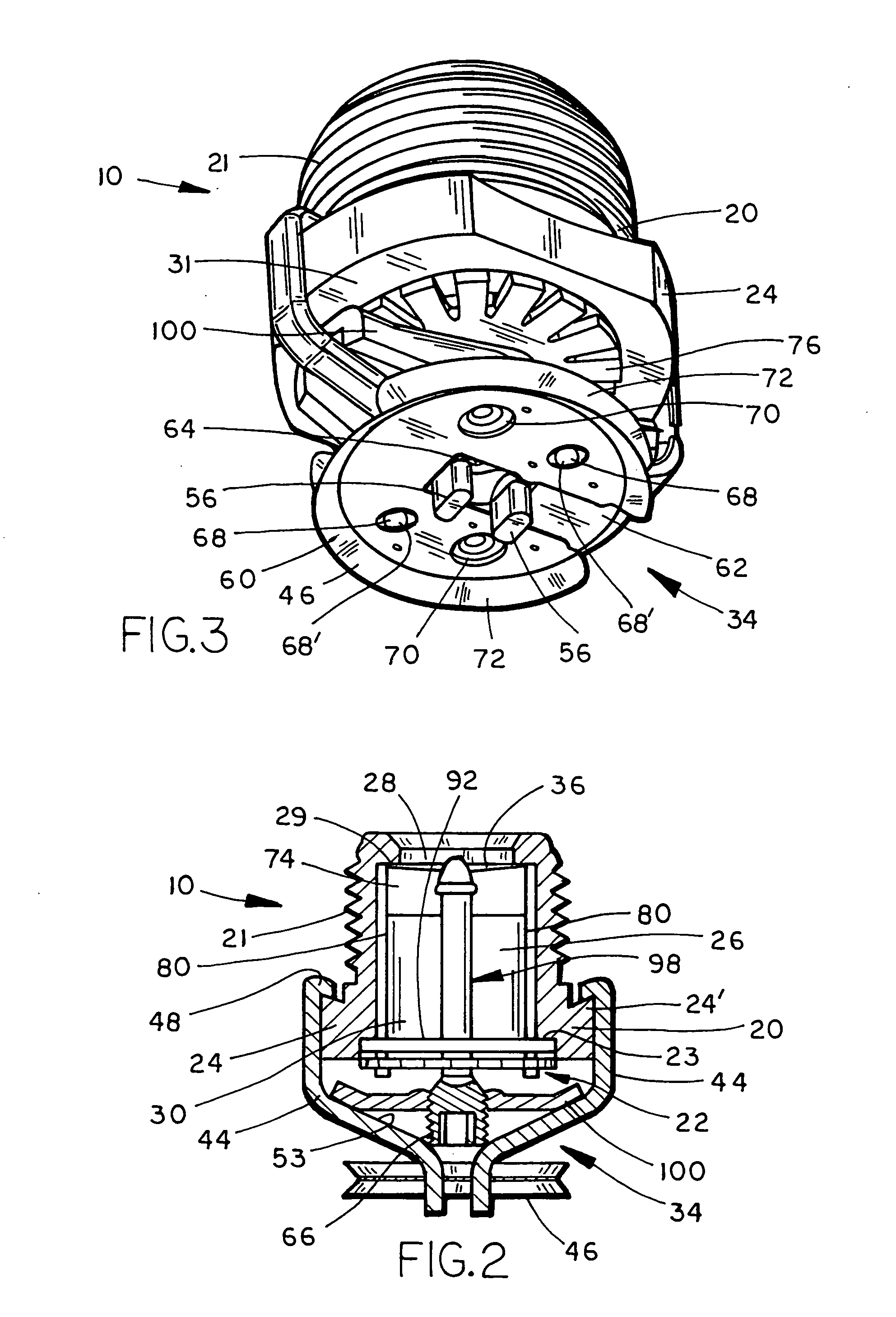
[0009] In one embodiment, the present invention overcomes the difficulties confronted by the prior art by providing a compact sprinkler head having a deflector assembly positioned within a body extension of the sprinkler head. According to one preferred aspect of the present invention, the sprinkler head includes a slidable deflector carried by at least one support arm a fixed distance from a retaining ring, with the deflector, at least one support arm, and retaining ring slidable within the body extension. Preferably, the sprinkler head includes a sprinkler body having an orifice, an inlet, and an outlet, with the body extension attached to the sprinkler body and having an extending section extending below the outlet. The retaining member is positioned between the bottom of the sprinkler head and within the body extension, while the deflector is positioned within the body extension with the at least one support arm attached to the retaining member. The retaining member is movable relative to both the sprinkler body and the body extension, while the at least one support arm maintains the deflector a fixed distance from the retaining member. A sealing assembly sealingly engages the outlet of the sprinkler body and is movable from a closed position wherein the sprinkler head is inactive to an open position wherein the sprinkler head is activated. A trigger assembly is carried by the body extension and operably connected with the sealing member. Configuring a sprinkler head to have a deflector movably positioned within a frame results in a compact sprinkler head which may be used in applications where space constraints must be observed, and eliminates the need for support pins attached to the deflector and residing external to the sprinkler body.
[0010] According to another preferred aspect of the invention, the deflector is monolithically formed with its support arms and the sprinkler head includes a sprinkler body, a body extension attached to the sprinkler body, a retaining member slidably positioned beyond the bottom surface of the sprinkler body and within the body extension, and a deflector. The deflector is positioned below the retaining member and is attached to the retaining member by the at least two support members projecting from the deflector towards the retaining member. A sealing assembly is configured to sealingly engage the outlet of the sprinkler body while a trigger assembly is carried by the body extension and operably connected with the sealing assembly. Providing a deflector positioned within the body extension reduces the diameter of the sprinkler head, while monolithically forming the deflector and the support members decrease its manufacturing cost.
[0011] According to yet another preferred aspect of the invention, a body extension is formed with an extending section having an annular rim while an annular retaining member, attached to a deflector, is slidably positioned within the body extension and captured by the annular rim. The sprinkler head includes a sprinkler body, and the body extension attached to the sprinkler body. The annular retaining member is positioned beyond the bottom of the sprinkler body, within the body extension, and has an outer periphery formed with at least one notch and a diameter greater than the diameter of the inwardly extending annular rim. The deflector is positioned within the body extension and has at least one support arm projecting therefrom. The support arm has an upper region dimensioned for receipt by the notch formed in the annular retaining member. A sealing assembly is configured to sealingly engage the outlet of the sprinkler body while a trigger assembly is carried by the body extension and operably connected with the sealing assembly. Providing an annular retaining member formed with notches for attachment to the deflector provides an effective and reliable structure without the use of externally mounted deflector pins. Additionally, the annular retaining member which is captured by the annular rim provides a reliable structure for moving the deflector to a preselected position upon activation of the sprinkler head.
[0012] In another preferred aspect of the invention, a sprinkler head includes a sprinkler body having a cavity, wherein the cavity has an inlet orifice, an outlet, and a trigger assembly carried by the sprinkler body. A sealing member is positioned within the cavity, while a slidable deflector support assembly is at least partially positioned within the cavity. The slidable deflector support assembly includes an annular ring and at least one attachment arm depending from the annular ring and attached to a deflector. A sealing assembly, carried by the sprinkler body is configured to urge the sealing member into engagement with the seat to thereby provide a fluid tight seal for the sprinkler body. Configuring a sprinkler head to have a sealing member positioned in fluid tight arrangement with the seat, and a deflector support assembly at least partially positioned within the cavity results in a compact sprinkler head which may be used in applications wherein space constraints must be observed.
[0013] In yet another preferred aspect of the invention, a sprinkler head includes a movable compression member that slides through a movable deflector. The sprinkler head preferably includes a body and a sealing member that closes the sprinkler orifice, with the compression member holding the sealing member in a closed condition. A trigger assembly holds the deflector and compression member in the closed position, and when activated permits the deflector to move away from the sprinkler body and the compression member to slide through the deflector. Placing the deflector and the compression member within the central cavity of the sprinkler body reduces the dimensions of the sprinkler head and thereby enables its use in applications requiring a compact sprinkler.


