Serial train communication system

a communication system and train technology, applied in the field of train communication system, can solve the problems of limited application within the railway, lack of built-in two-way communication capability, and use of heavy 6 to 8-gauge wires, and achieve the effect of reducing capital investment and expenditur

Inactive Publication Date: 2005-06-09
WABTEC HLDG CORP
View PDF5 Cites 63 Cited by
  • Summary
  • Abstract
  • Description
  • Claims
  • Application Information

AI Technical Summary

Benefits of technology

[0031] It is yet a further object of the present invention to provide a serial train communication system utilizing a sound transmission means which has capabilities for future interface with EP and ECP braki

Problems solved by technology

While offering a direct brake release and improved air pressure consumption, most of these systems use a second train line for main reservoir air supply and they do not have built-in two-way communication capabilities.
There are also several disadvantages of the current ECP braking systems causing limited application within railways.
An additional disadvantage is the use of heavy 6 to 8 gage wire, potentially shielded from transients and other noise inducing factors.
In a second aspect, a greater brake shoe wear has been documented due to a more frequent use of the brakes.
In a fourth aspect, ECP braking system requires significant capital expenditures due to high implementation costs.
Even though the system was first introduced in 1993, the Return On Investment (ROI) has not yet been fully realized.
Several other

Method used


Image

  • Serial train communication system
  • Serial train communication system
  • Serial train communication system

Examples


Embodiment Construction

[0040] Prior to proceeding with the more detailed description of the invention it should be noted that for the sake of clarity and understanding the invention, identical components which have identical functions have been identified with identical reference numerals throughout the several views illustrated in the attached drawing Figures, unless otherwise noted.

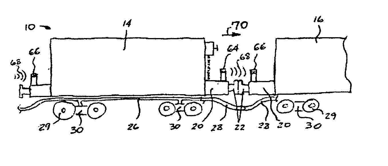
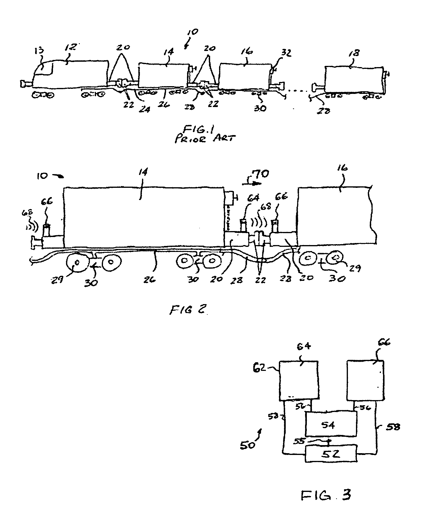
[0041]FIG. 1 shows a railway train, generally designated 10, having at least one locomotive 12 with a cab 13 and a predetermined plurality of railway cars 14 through 18 serially coupled to such at least one locomotive 12. As can be understood, railway trains and, particularly, railway freight trains can operate many more cars than shown, and typically, one-hundred to two-hundred and fifty railway freight car trains are not uncommon. While FIG. 1 only depicts three railway cars 14-18 and one locomotive 12, it is to be understood that multiple railway cars of any length can be used in practicing the invention.

[0042] The at le...


PUM


Abstract

A serial train communication system employs a pair of ultrasonic transceivers oppositely mounted at each end of a railway car. Each ultrasonic transceiver is coupled to a controller and to an independent power source. The controller is further coupled to various apparatuses installed on the railway car and is capable of controlling operation thereof. A command signal sent from a locomotive cab travels between railway cars enabling control of various apparatuses of such railway cars and status signals from such apparatuses may be sent back to a locomotive cab event recorder. The controller and the power source may be attached to the railway car or to any such apparatus. In another embodiment, a single ultrasonic transceiver is installed within an air brake pipe enabling communication within a mixed railway car configuration.

Description

CROSS-REFERENCE TO RELATED APPLICATIONS [0001] This application is related to and claims priority from U.S. Provisional Patent Application Ser. No. 60 / 527,505 filed on Dec. 5, 2003.FIELD OF THE INVENTION [0002] The present invention relates, in general, to a train communication system and, more particularly, the instant invention relates to a serial train communication system for a railway train consisting of at least one locomotive and a predetermined plurality of railway cars coupled thereto and, yet more particularly, the invention relates to a serial train communication system utilizing sound transmission and, still more particularly, the present invention relates to a serial train communication system utilizing sound transmission for controlling brakes of the railway car. BACKGROUND OF THE INVENTION [0003] The following background information is provided to assist the reader to understand the environment in which the invention will typically be used. The terms used herein are n...

Claims


Application Information

Patent Timeline
IPC IPC(8): B61L15/00
CPCB61L15/0027
Inventor RING, MICHAEL E.
Owner WABTEC HLDG CORP
Why Eureka
Try Eureka