Integrated laryngoscope and suction device

Inactive Publication Date: 2007-12-13
DP MEDICAL
View PDF29 Cites 56 Cited by
  • Summary
  • Abstract
  • Description
  • Claims
  • Application Information

AI Technical Summary

Benefits of technology

[0012]Embodiments of the invention herein described will help overcome the difficulties posed by obscuring fluids during endotracheal intubation. In one embodiment, a laryngoscope with a suction unit internal to the handle is provided, allowing for maximum portability while removing th

Problems solved by technology

This increases the success rate of intubations and d

Method used


Image

  • Integrated laryngoscope and suction device
  • Integrated laryngoscope and suction device
  • Integrated laryngoscope and suction device

Examples


Embodiment Construction

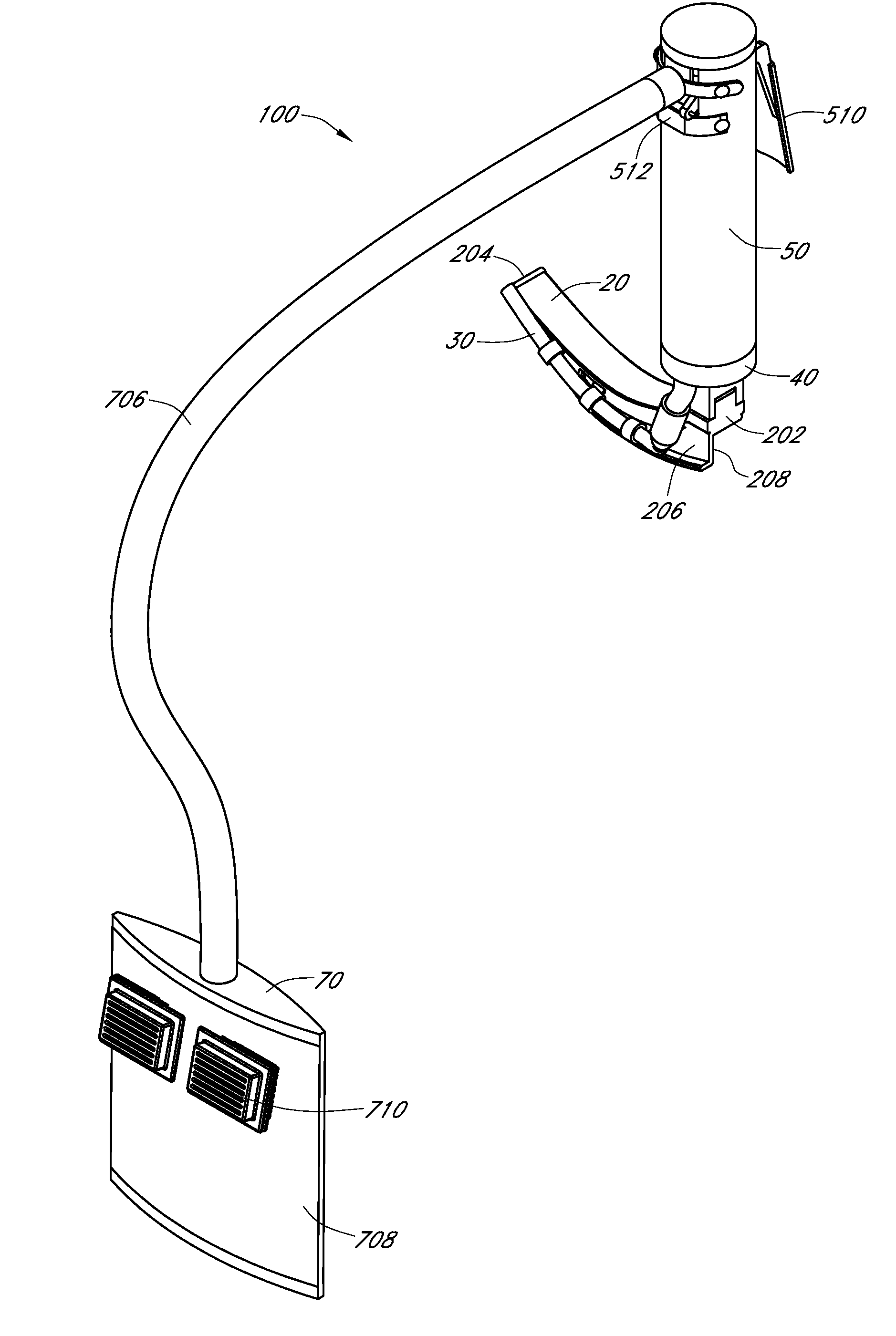
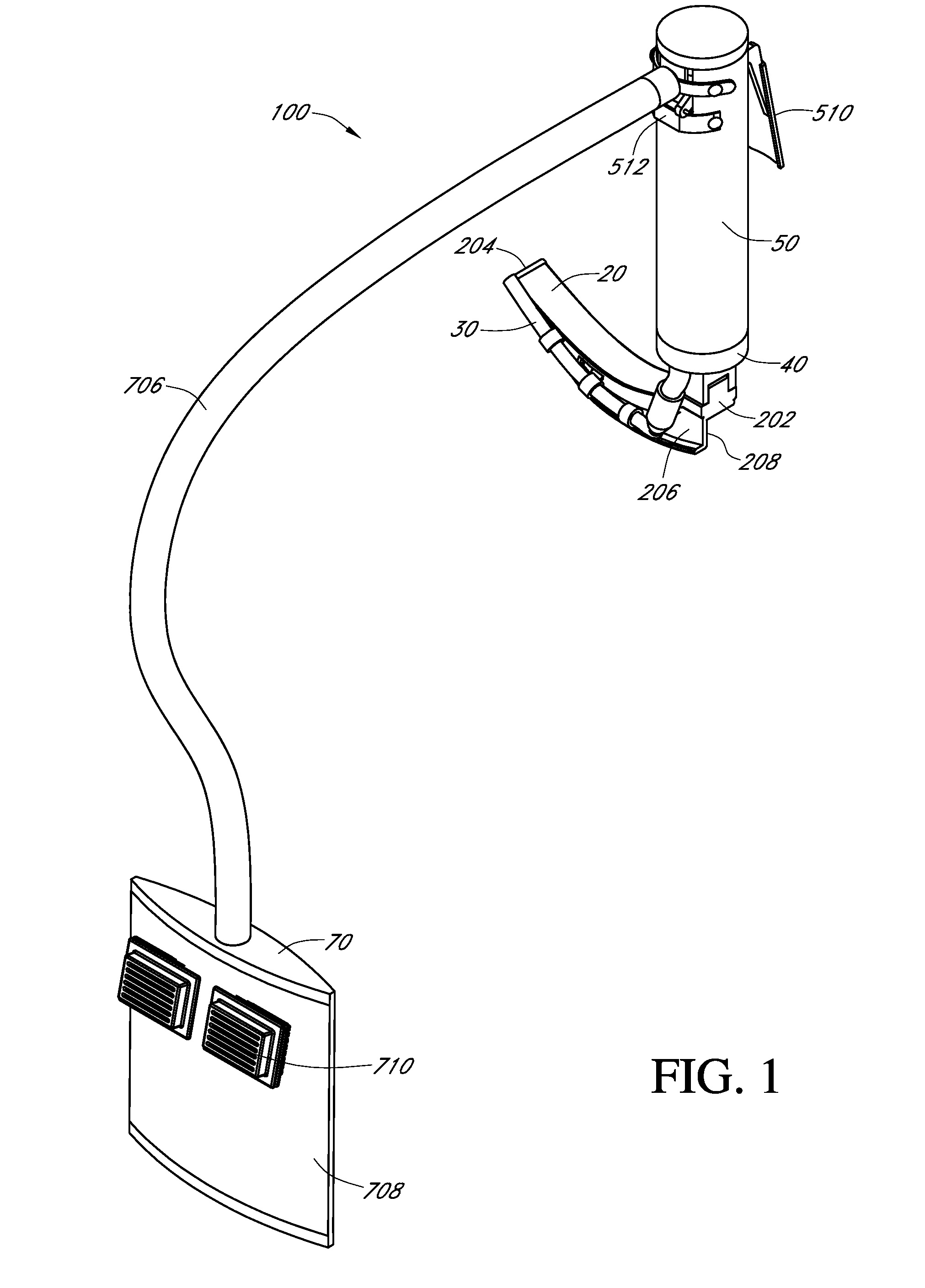
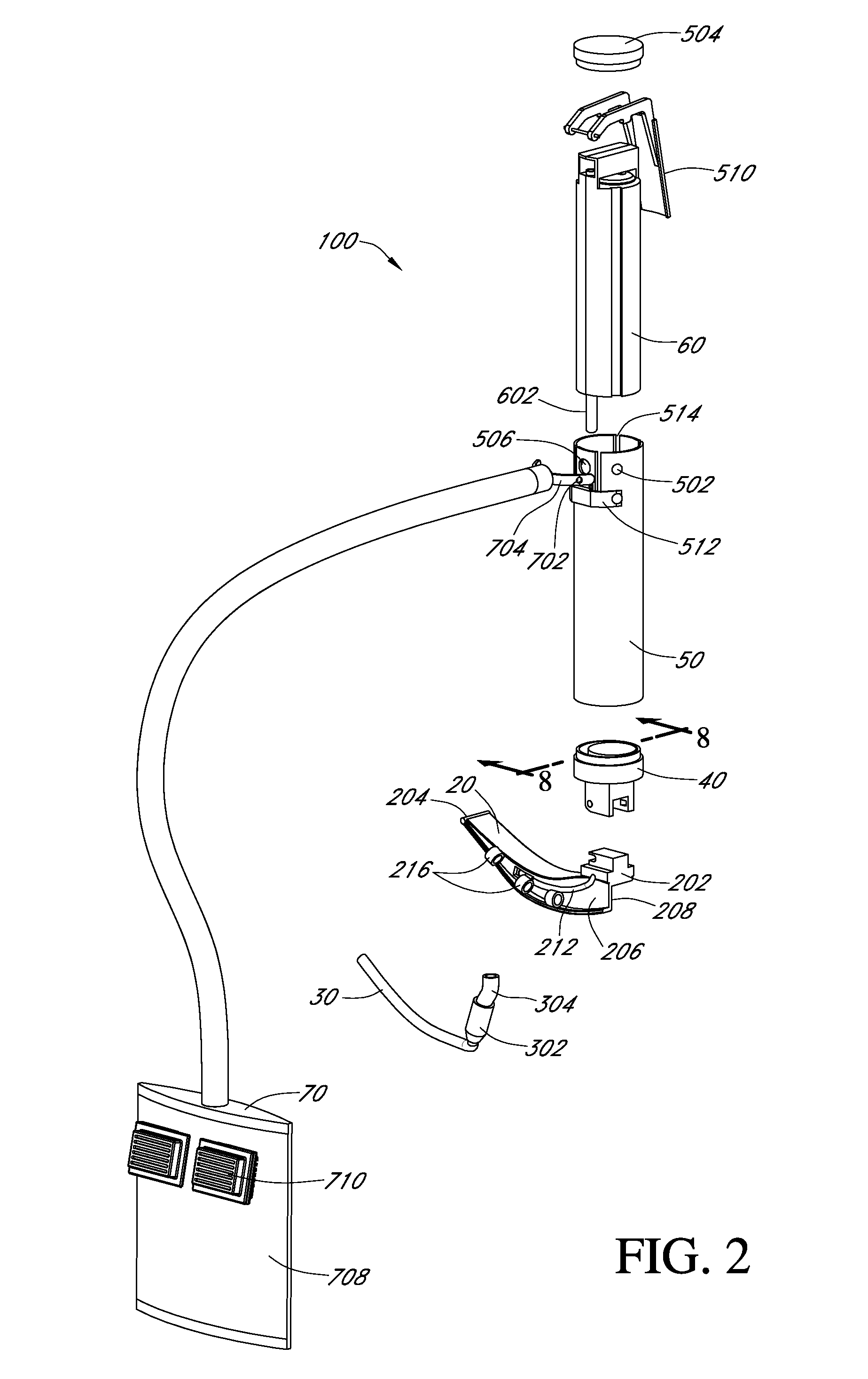
[0035]One embodiment of the invention is a laryngoscope with internal suction capability. All suction generating components may be located inside the handle. The laryngoscope includes a blade, and may have a tube that runs the length of the blade to the distal end, allowing a user to suction fluids without changing devices or requiring external suction units. The entire suction unit may be housed in the handle.

[0036]Embodiments with the suction unit inside the handle have particular advantages, such as allowing a user the ability to operate both the laryngoscope and the suction unit with the same hand, without removing the laryngoscope blade, even in an environment where no external suction generating unit is easily accessible. By housing the suction unit within the handle, embodiments of the invention advantageously avoid extra tubes and extra bulk near a patient's mouth, improving a user's ability to properly position the laryngoscope during an intubation procedure. Additionally, ...


PUM


Abstract

A suction unit is placed inside the handle of a laryngoscope to allow portable suction to be utilized during intubation without requiring multiple devices. The suction tip can be attached to the distal end of the laryngoscope blade. Replacing the light on a laryngoscope with an LED allows for a small watch-sized battery to be used instead of current large batteries taking up the handle space. This opens up the handle space to make room for the suction unit. Evacuated fluids and discharge exit into a tube and into a portable receptacle.

Description

RELATED APPLICATIONS[0001]This application claims priority to Provisional Application No. 60 / 804,312, entitled INTEGRATED LARYNGOSCOPE, filed Jun. 9, 2006. The subject matter of the aforementioned application is hereby incorporated herein by reference in its entirety.BACKGROUND OF THE INVENTION[0002]1. Field of the Invention[0003]This invention relates to the field of laryngoscopes and portable suction generating devices.[0004]2. Description of the Related Art[0005]Endotracheal intubation is a common medical procedure wherein a hollow tube is inserted down the throat, through the vocal chords and into the lungs to provide an open airway for ventilation. To perform this procedure orally, the intubator must be able to visually see the vocal chords in order to properly insert the endotracheal tube (ETT). If, for any reason, the vocal chords cannot be seen, the procedure cannot continue.[0006]A device called a laryngoscope is used to move the tongue and lift the epiglottis to visualize ...

Claims


Application Information

Patent Timeline
IPC IPC(8): A61B1/267
CPCA61B1/00094A61B1/00108A61B1/2673A61B1/0676A61B1/0684A61B1/015
Inventor LOVELL, NATHANPERRY, SCOTTNELSON, JESSICAOLSEN, EMILYJAQUES, RYAN
Owner DP MEDICAL
Why Eureka
Try Eureka