Method and apparatus for providing telecommunications services

a technology for telecommunication services and telephone calls, applied in the direction of data switching networks, digital transmission, interconnection arrangements, etc., can solve the problems of frequent routing changes, high cost and time consumption, and the inability to modify present-day switches to accept such special interfaces

Inactive Publication Date: 2005-01-11
AMERICAN TELEPHONE & TELEGRAPH CO
View PDF7 Cites 62 Cited by
  • Summary
  • Abstract
  • Description
  • Claims
  • Application Information

AI Technical Summary

Benefits of technology

The method of the invention advantageously overcomes the difficulty of accommodating different switches from different vendors with different routing translations within the same network. In accordance with the invention, each switch queries the central routing database using the TCAP query protocol normally used by the switch for other database queries. Other query protocols, such as SIP or Parlay could also be employed. The switch making the query receives a DPC to initiate the connection with the next switch. The switch itself performs the necessary connection translations in response to DPC received from the routing database. Thus, the centralized routing database need not concern itself with particular type of switch, only with the destination of the call. Thus, only one version of the routing translation need be provisioned in the routing database, avoiding the need to provision the routing translation in each switch in accordance with the particular format established by the switch vendor.

Problems solved by technology

Thus, in a telecommunications network that embodies multiple switches using different technologies, such as Circuit-switching, ATM switching or IP routing, often from different vendors, making routing changes becomes very cumbersome.
Unfortunately, with growing demand for telecommunications services, routing changes occur frequently, as new switches are deployed.
Implementing these techniques requires the development of new interfaces to allow present-day switches to receive the information from the separate call processing application platform since present day switches are not presently adapted to do so.
Modifying present day switches to accept such special interfaces could prove expensive and time consuming.

Method used


Image

  • Method and apparatus for providing telecommunications services
  • Method and apparatus for providing telecommunications services
  • Method and apparatus for providing telecommunications services

Examples


Embodiment Construction

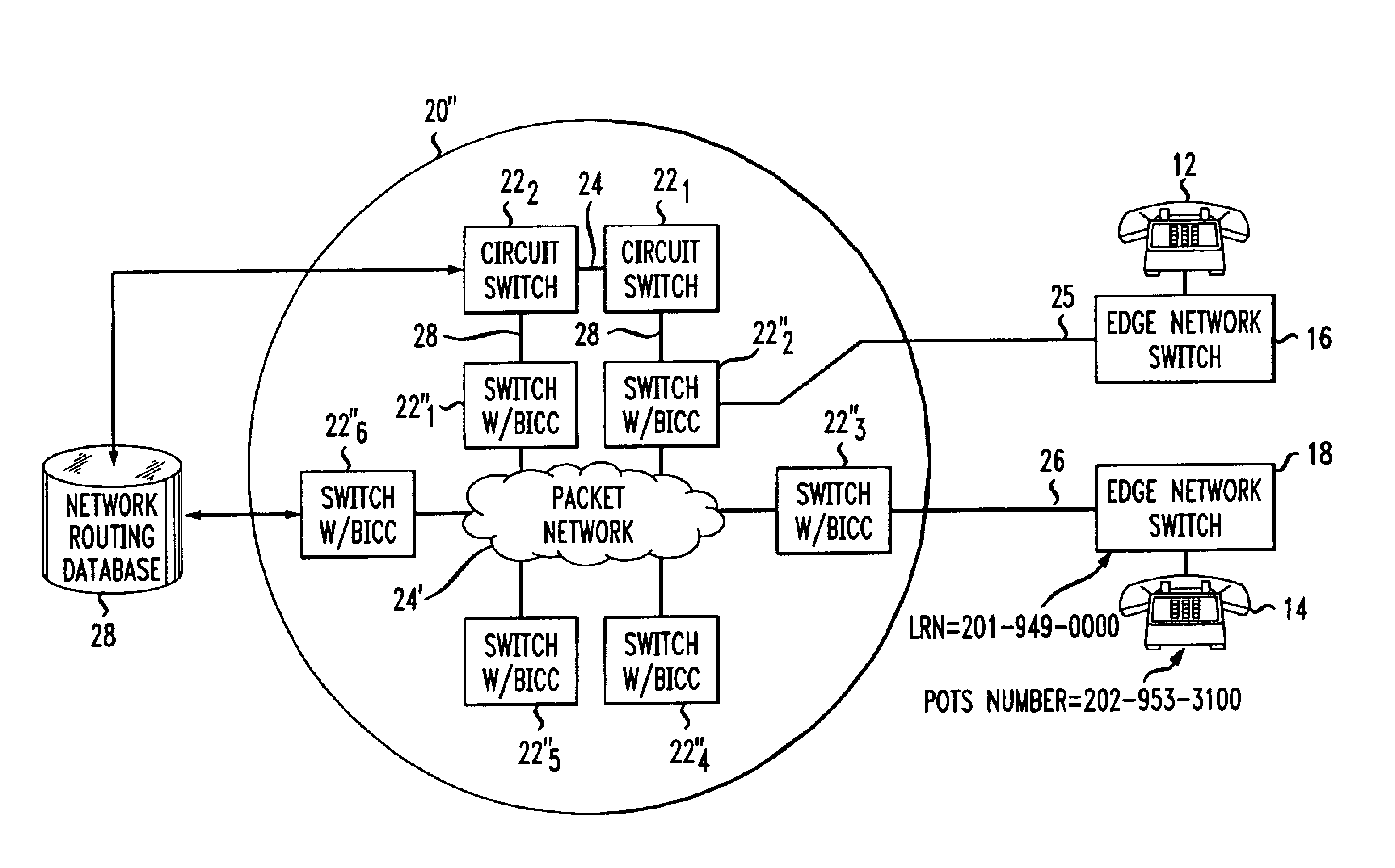
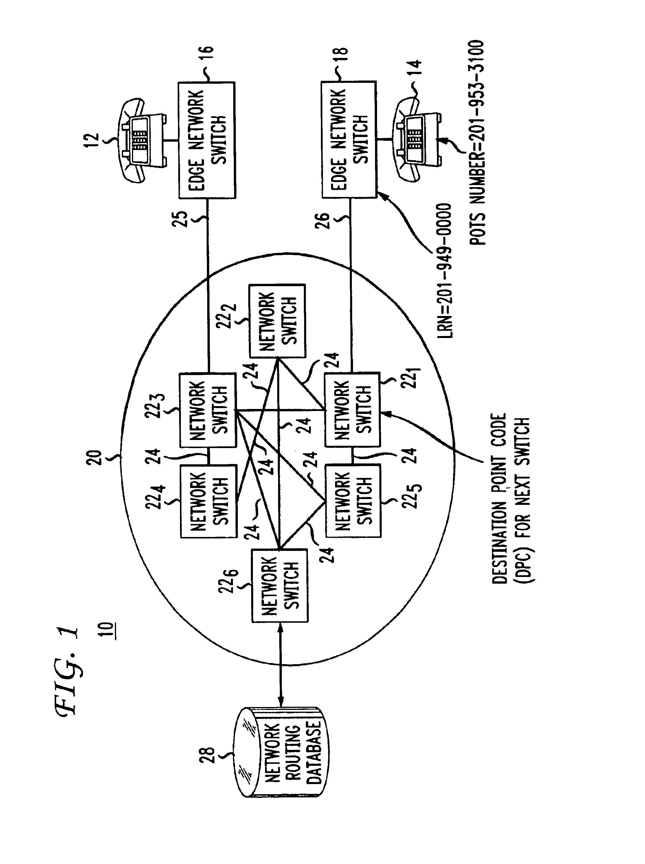
FIG. 1 depicts a block schematic diagram of a circuit-switched telecommunications network 10 for routing a telephone call from a calling party, represented by a first telephone set 12, to a called party, represented by a second telephone set 14. In the illustrated embodiment of FIG. 1, the telephone sets 12 and 14 receive local telephone service (e.g., dial tone) from edge switches 16 and 18, respectively, each linked to, but lying outside and at the edge of an Inter-exchange Carrier (IXC) network 20, such as the inter-exchange network maintained by AT&T. In practice, each edge switch may comprise a class 5 central office switch, such as the 5ESS switch now manufactured by Lucent Technologies, Inc., or a DMS 100 switch manufactured by Nortel Networks, Inc. The edge switches 16 and 18 could belong to a single provider of local service, or could belong to separate local service providers. Alternatively, one or both of the edge switches 16 and 18 could serve as an extension of the IXC ...


PUM


Abstract

To facilitate routing changes, a telecommunications network (10, 10′, 10′″) includes a centralized network routing database (28) queried by each ingress switch upon receipt of a call by a calling subscriber (12). In response to the query, the network routing database returns to the querying switch the identity on the next (downstream) switch in the routing path. The querying switch then translates the switch identity to establish the link to that next switch. Because each querying switch makes the necessary translation of the next switch identity to make the link to the next switch, the centralized network database need not concern itself with the particular characteristics of the switch. To make global routing changes, only the network routing database need be updated, not each individual switch.

Description

TECHNICAL FIELDThis invention relates to a technique for routing telephone calls in a communications network with simplified administration of routing data.BACKGROUND ARTIn present day telecommunications networks, an incoming call, dialed by a calling party to a called party, enters the network at an ingress switch serving the calling party. The ingress switch routes the call to a terminating switch serving the called party, either directly, or through one of more intermediate (via) switches. In order to route a call, each switch typically performs a translation to establish a route list of trunks capable of carrying the call to the next switch. Often, multiple trunks link the various switches in a network, so call routing not only involves selecting the next switch, but also selecting the particular idle trunk linking the switches. Presently, each switch makes its own routing decisions. Thus, in a telecommunications network that embodies multiple switches using different technologi...

Claims


Application Information

Patent Timeline
Patent Type & Authority Patents(United States)
IPC IPC(8): H04M7/00H04Q3/00
CPCH04Q3/0045H04M7/128
Inventor ANDROSKI, FRANK J.BHAGAT, PROMOD KUMARFISHMAN, SAUL DANIELGANESAN, SEKARSAYERS, SCOTT A.SHETH, SMITA PRADIP
Owner AMERICAN TELEPHONE & TELEGRAPH CO
Why Eureka
Try Eureka