Sectional toolbar for a planter

a toolbar and planter technology, applied in the field of agricultural devices, can solve the problems etc., and achieve the effect of high cost of complexity, maintenance, reliability

Inactive Publication Date: 2005-04-28
BAUER VAUGHN L
View PDF22 Cites 64 Cited by
  • Summary
  • Abstract
  • Description
  • Claims
  • Application Information

AI Technical Summary

Benefits of technology

[0012] An advantage of the present invention is the use of a five-section toolbar. Because farm fields are not perfectly planar, to ensure the planter units contact the soil, flexibility must be built into a planter toolbar. Ideally, each unit would “float,” such that it could be in contact with the soil, irrespective of the soil level for any other unit. A toolbar with only two units per section could provide this ideal flexibility, but at a high cost of complexity, maintenance, and reliability. A compromise is to divide the toolbar into as many sections as practical. For the present invention, that number of sections is more than three and, typically, five.
[0013] An additional advantage of the present invention is the horizontal (that is, within a substantially horizontal plane) folding of a five or more section toolbar for transport on public roads and through narrow gateways. The present invention uses a telescoping tongue similar or identical to the three-section toolbars, but has overcome the difficulty of the additional pivot points. When in transport mode, the wing sections are borne by the tongue. The tongue, in turn, is supported at its forward end by the tractor draw bar, and its rearward end by wheels situated near the rear end of the tongue. At the extreme ends of the toolbar, as well as at each sectional pivot point, a latch is provided for transferring the weight of the wing sections to the tongue. Wheels at each pivot point and at the extreme ends of the wings carry the weight of the wing sections when the implement toolbar is extended in its field position. Actuators between the wheels and the toolbar raise the toolbar relative to the wheels for folding. Once the wings have arrived in their forward positions, the wing sections are lowered so the latches carry their weight on the tongue and the wheels are raised off the surface.
[0014] Between each of the toolbar sections is a pivot point allowing the sections to be noncollinear with one another for the purpose of following the ground contour.

Problems solved by technology

A toolbar with only two units per section could provide this ideal flexibility, but at a high cost of complexity, maintenance, and reliability.

Method used


Image

  • Sectional toolbar for a planter
  • Sectional toolbar for a planter
  • Sectional toolbar for a planter

Examples


Embodiment Construction

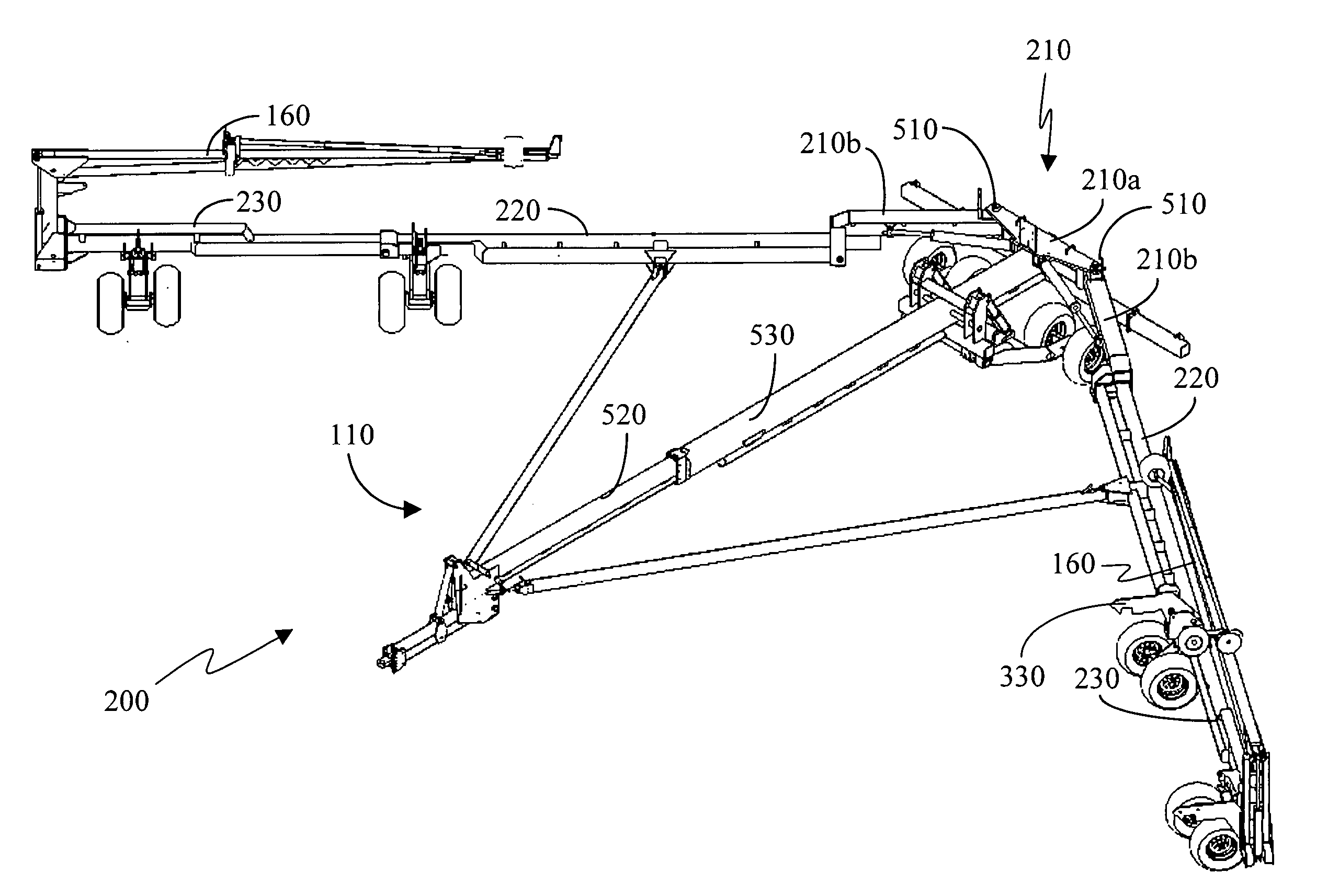
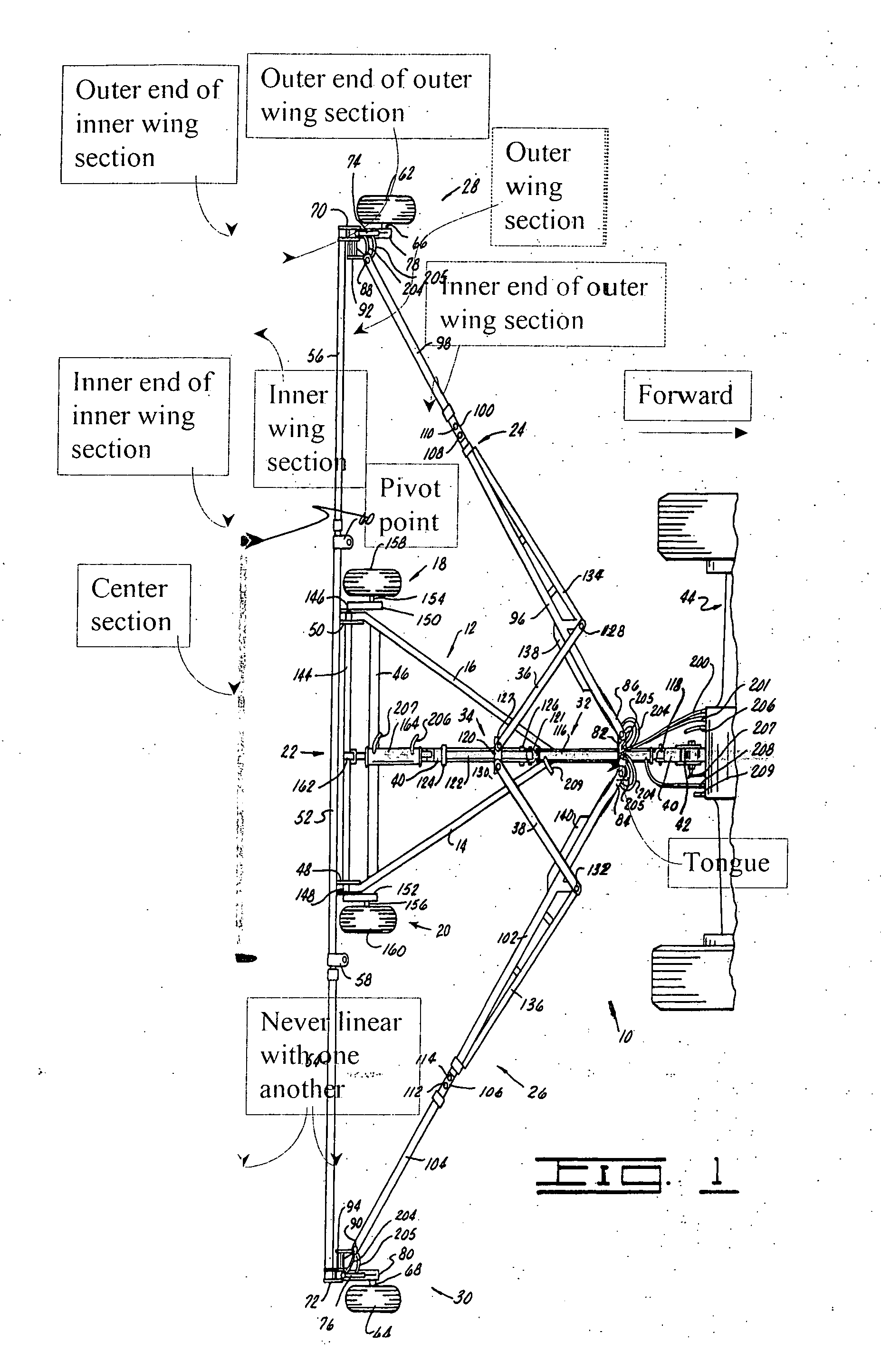
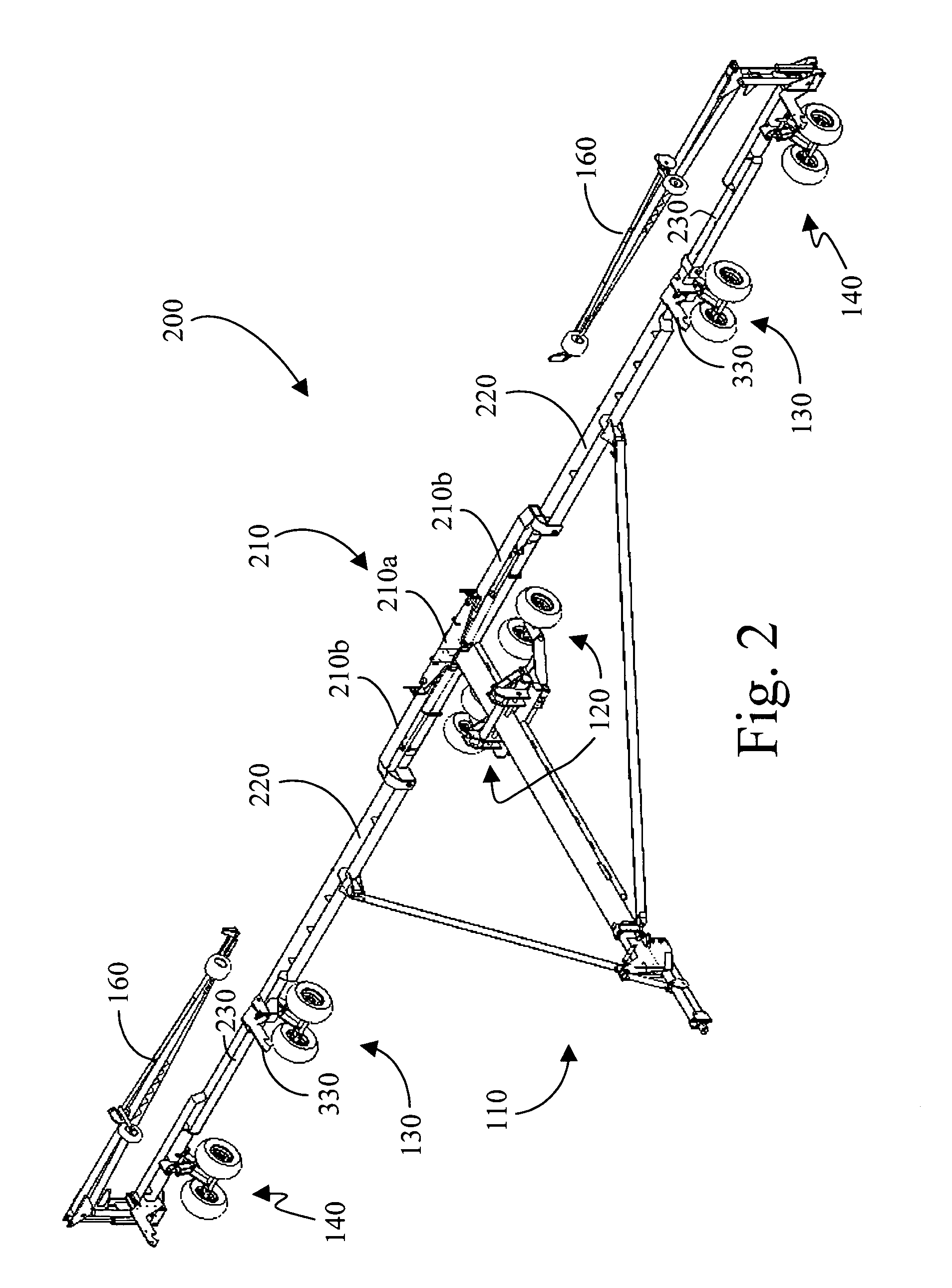
[0028] A complete planter 100 is shown in FIG. 1. The planter 100 is drawn by a tractor or other vehicle by its tongue 110, which is telescopic and an integral part of the foldability of the planter for road transport, gate access, and storage.

[0029] A center wheel assembly 120 carries the weight of the tongue 110 and the center portion of the planter 100. During transport, the center wheel assembly 120 carries all the weight carried by wheels on the planter.

[0030] Center wing wheel assemblies 130 support weight in between the tongue 110 of the planter 100 and the ends of the planter 100.

[0031] End wing wheel assemblies 140 bear the weight of the ends of the planter 100.

[0032] Planter units 150, with containers carrying seed, and the components for opening the ground, dropping the seed, and compacting the soil around the seeds are shown lined up across the planter 100.

[0033] Markers 160 provide a gage line for aligning the tractor and planter for each trip across the field.

[00...


PUM


Abstract

Implement toolbars as used for planters have become very long in recent years. In order to assure good ground contact, the long toolbar of the present invention is divided up into more than three sections, including a center section and wing sections. The wing sections fold forward for transport on public roads, over field accesses, and through gates. The resulting planter can be longer than prior art planters while providing sound ground contact and a compact transport mode.

Description

CROSS REFERENCE TO RELATED APPLICATIONS [0001] Not applicable. STATEMENT REGARDING FEDERALLY SPONSORED RESEARCH OR DEVELOPMENT [0002] Not applicable. REFERENCE TO MICROFICHE APPENDIX [0003] Not applicable. BACKGROUND OF THE INVENTION [0004] 1. Field of the Invention [0005] The present invention relates generally to an agricultural device. More particularly the present invention relates to a planter toolbar comprising more than three sections, and is horizontally foldable. [0006] 2. Background Art [0007] Fences are being removed in the corn belt. For this reason and because the acreage farmed by the typical farmer is increasing, field equipment, in particular planters, are being built to cover more and more crop rows as the years go by. Roads, however, are not being significantly widened. Therefore, schemes for folding or rotating wide equipment have been devised for the purpose of transporting this large machinery on public roads. [0008] An additional consideration is that farm grou...

Claims


Application Information

Patent Timeline
Patent Type & Authority Applications(United States)
IPC IPC(8): A01B73/06A01C7/20
CPCA01C7/208A01B73/065
Inventor BAUER, VAUGHN L.
Owner BAUER VAUGHN L
Why Eureka
Try Eureka