Energy efficient pyrolytic processing oven

a pyrolysis and processing oven technology, applied in the field of waste treatment, can solve the problems of unreliable and energy inefficient ovens, and achieve the effects of reducing energy consumption, high maintenance, and high energy efficiency

Inactive Publication Date: 2006-04-25
EDMONDSON JERRY M
View PDF5 Cites 11 Cited by
  • Summary
  • Abstract
  • Description
  • Claims
  • Application Information

AI Technical Summary

Benefits of technology

[0009]My invention through the disclosure of a configuration that eliminates the energy consuming, high maintenance, complex mechanisms normally associated with pyrolysis ovens, makes available an oven that is highly energy efficient, easy to maintain and is safe. The oven disclosed

Problems solved by technology

The central component to successful pyrolytic conversion is the oven and all of the ove

Method used


Image

  • Energy efficient pyrolytic processing oven
  • Energy efficient pyrolytic processing oven

Examples


Embodiment Construction

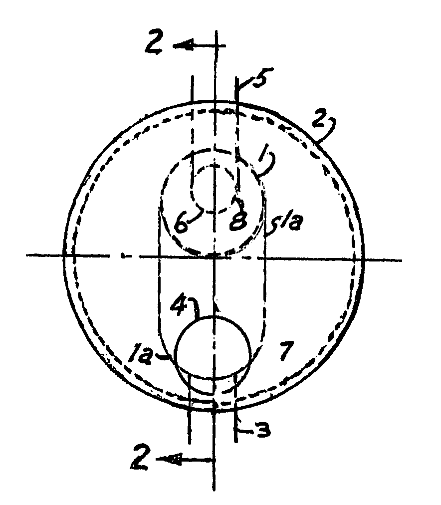
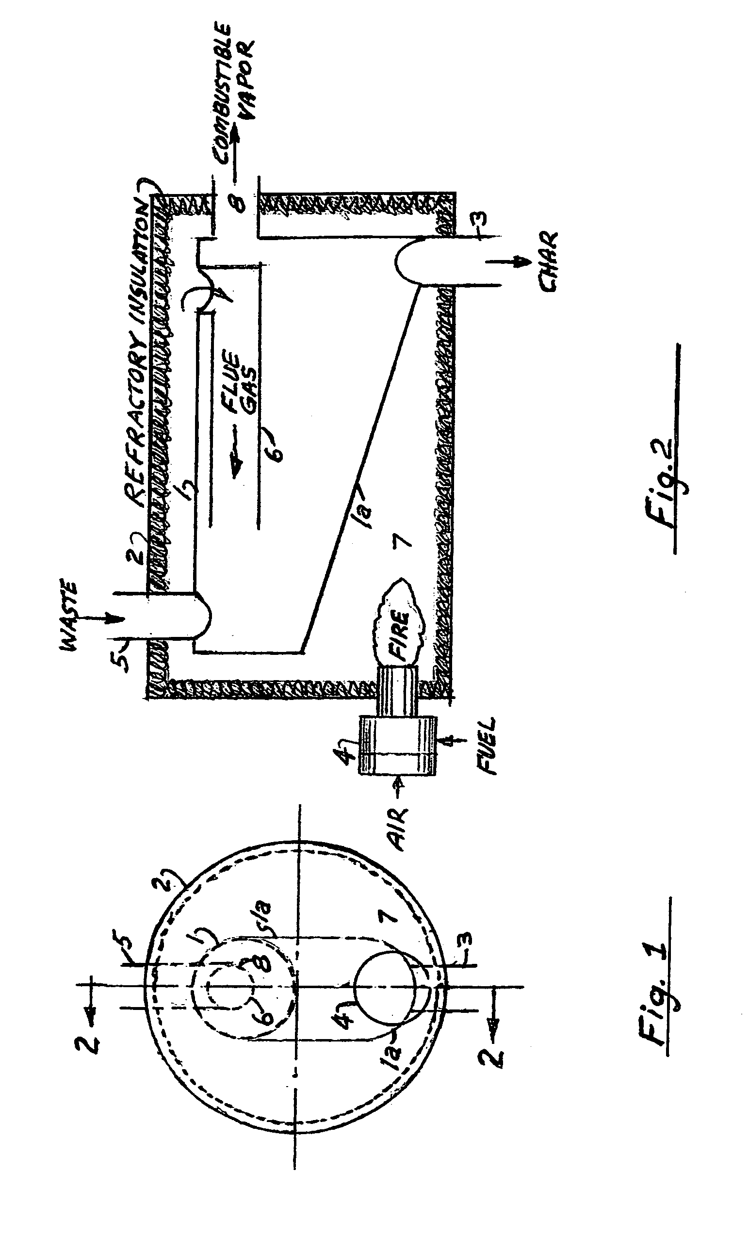
[0011]Referring to the drawing, the pyrolytic processing oven consists of a containment vessel 1 suspended inside of a heated refractory insulated vessel 2. The vessel 1 is configured in a unique way so that the bottom 1a forms a chute within which pyrolized material can slide to the char outlet 3.

[0012]Heat is provided by a fired heating means 4 whereby part of the heat for the pyrolysis process is provided via heat transfer from the flame and the products of combustion (flue gas) through the wall of the containment vessel 1 and part of the heat is provided by direct contact of the waste material entering into the vessel 1 through the inlet conduit 5 by the hot flue gases which are routed through the flue gas conduit 6. The direct contact of the waste material with the hot flue gas improves the heat exchange process and speeds up the pyrolysis of the waste material and facilitates the movement of the char to the char outlet. The unique shape of the vessel 1 with its obround and slo...


PUM


Abstract

A method and apparatus of converting waste materials into combustible vapor and char utilizing an energy efficient pyrolytic processing oven that eliminates the complex mechanisms usually associated with these systems for heating and transporting the waste material through the oven. The oven of this system has a unique configuration that permits the pyrolized material to free fall through the unit.

Description

BACKGROUND OF THE INVENTION[0001]1. Field of the Invention[0002]The present invention relates to the treatment of waste and more particularly methods and apparatuses utilizing pyrolysis.[0003]2. Discussion of Prior Art[0004]Walker U.S. Pat. No. 6,619,214 describes a common method and apparatus used in pyrolytic processing of waste. It will be noted that much emphasis is placed on the configuration of the “oven”, generally referred to as the “thermal reactor”, and the complex mechanisms for conveying the material to be pyrolized through the oven. It has been found that the complexity of the conveying means and the high extent of maintenance and high energy cost, required to keep the mechanisms operable, doom such systems to economic failure.[0005]3. Discussion of the Present Invention[0006]My invention discloses a type of oven that will eliminate the complex conveying mechanisms and high energy and maintenance cost. The oven of my invention is of a unique shape that affords conveyanc...

Claims


Application Information

Patent Timeline
IPC IPC(8): F23B90/00
CPCF23G5/027F23G2209/281F23G2209/20
Inventor EDMONDSON, JERRY M.
Owner EDMONDSON JERRY M
Why Eureka
Try Eureka