Method for checking the correct installation of a bend-insensitive optical cable and optical cable suitable for the method thereof

a technology of bend-insensitive optical cables and optical cables, which is applied in the direction of optical elements, optical apparatus testing, instruments, etc., can solve the problems of not generating measurable optical attenuation within the wavelength, increasing the risk of higher repair and maintenance costs, and achieving cost-effective effects

Active Publication Date: 2013-06-06
PRYSMIAN SPA
View PDF0 Cites 9 Cited by
  • Summary
  • Abstract
  • Description
  • Claims
  • Application Information

AI Technical Summary

Benefits of technology

[0018]In compliance with the always more stringent requirements of bend insensitiveness for optical fibres, recent developments for FTTP applications are directed to highly bend-insensitive optical fibres. The Applicant has observed that, if the fibre is highly bend-insensitive, even a mechanically dangerous bend would not generate a measurable optical attenuation within the wavelength range of signal transmission, at least when using standard equipment for in-field testing. Therefore, if on one hand bend-insensitivity is required to guarantee cost-effective installation and optical performance, on the other hand, it may preclude early in-field detection of harmful bends, thereby increasing the risk of higher repair and maintenance costs.

Problems solved by technology

The Applicant has observed that, if the fibre is highly bend-insensitive, even a mechanically dangerous bend would not generate a measurable optical attenuation within the wavelength range of signal transmission, at least when using standard equipment for in-field testing.
Therefore, if on one hand bend-insensitivity is required to guarantee cost-effective installation and optical performance, on the other hand, it may preclude early in-field detection of harmful bends, thereby increasing the risk of higher repair and maintenance costs.

Method used

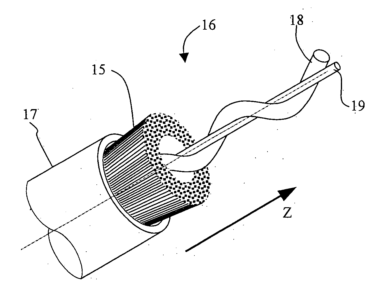
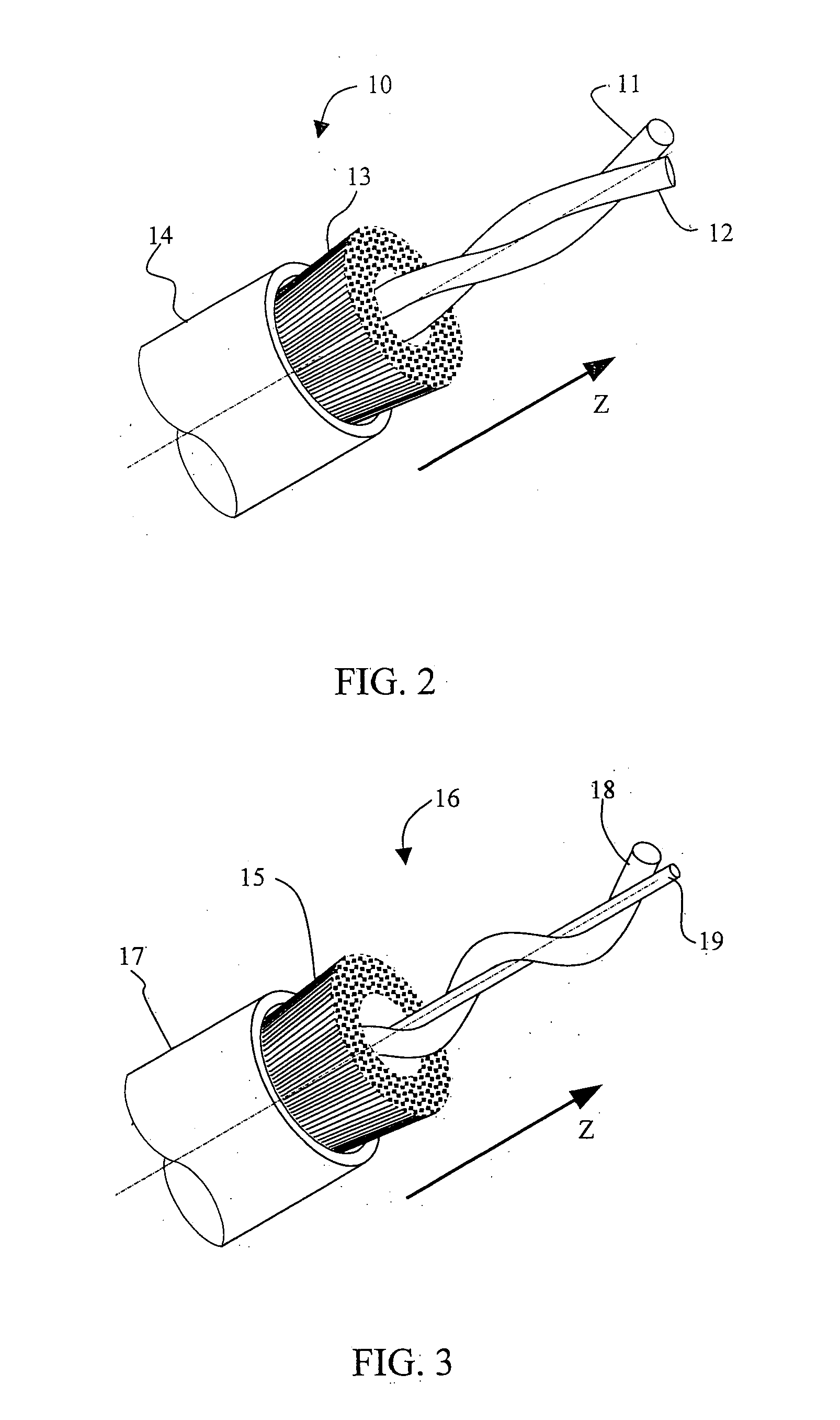

Image

  • Method for checking the correct installation of a bend-insensitive optical cable and optical cable suitable for the method thereof
  • Method for checking the correct installation of a bend-insensitive optical cable and optical cable suitable for the method thereof
  • Method for checking the correct installation of a bend-insensitive optical cable and optical cable suitable for the method thereof

Examples


Embodiment Construction

[0061]Bend-insensitive optical cables comprising single-mode optical fibres are often tailored to FTTP applications, where they are provided in houses, offices, and other premises for telecommunication services, such as broadband Internet, video-on-demand and high-definition IPTV. An access distribution can be deployed on a single floor of a building or generally installed in a multi-story building in order to bring optical fibres to individual subscribers on different floors. For example, in a multi-store building, a distribution network may comprise a MDU placed on the building's basement from which a riser cable traverse the vertical rise of the building and segments of the cable are dropped at each floor. Alternatively, the distribution cable can be routed from an optical network unit and is spliced up at a plenum cable entrance facility in a plurality of drop cables that then reach different houses of individual subscribers.

[0062]Installation routes of drop cables often include...


PUM

PropertyMeasurementUnit
cut-off wavelengthaaaaaaaaaa
test wavelengthaaaaaaaaaa

Abstract

A method for detecting faulty laying down of an optical cable exhibiting a measured cut-off wavelength includes providing an optical cable for transmitting optical signals including at least one single-mode optical fibre having an attenuation equal to or larger than a first threshold value as measured when wound for one turn around a bending radius equal to or smaller than 5 mm at at least one predetermined test wavelength, the test wavelength being smaller than the measured cut-off wavelength, and an attenuation smaller than a second threshold value as measured when wound for one turn around a bending radius equal to at least a minimum bending radius at an operative wavelength equal to or larger than the measured cut-off wavelength; laying the optical cable; and measuring the attenuation in the at least one optical fibre at the predetermined test wavelength. An optical cable includes at least one optical fibre that is bend sensitive at a predetermined test wavelength not larger than the measured cut-off wavelength and is bend insensitive at an operative wavelength larger than the measured cut-off wavelength, where the cable operates in single-mode regime.

Description

TECHNICAL FIELD[0001]The present invention relates to a method for checking the installation and / or the laying of a bend-insensitive optical cable and to an optical cable that is bend-insensitive when operating in single-mode regime.BACKGROUND OF THE INVENTION[0002]The use of single-mode optical fibres in fibre-to-the-premises (FTTP) applications, including fibre-to-the-home (FTTH) and fibre-to-the-building (FTTB) applications, generally require low bending loss of optical signals transmitted through the fibres, also under stringent installation constraints that may impose tight bend radii, e.g., due to sharp cornering in buildings or compression of optical fibres. In particular, cabling and hardware applications aimed to miniaturize passive field equipment, e.g., local convergence cabinets or storage boxes, and the development of multi-dwelling units (MDUs) require fibre designs with superior bending capabilities. In addition, coarse wavelength division multiplexing systems (CWDM) ...

Claims


Application Information

Patent Timeline
Patent Type & Authority Applications(United States)
IPC IPC(8): G02B6/44G01N21/84
CPCG01M11/088G01M11/3109G02B6/4401G02B6/4463G01N21/84G02B6/4413G02B6/50
Inventor RUZZIER, MARCOCATTELAN, SUSANNAMACCHETTA, ANDREACOLLARO, ANTONIOCARONNA, VALERIA
Owner PRYSMIAN SPA
Why Eureka
Try Eureka