Process for producing microfiber assembly

a technology of microfibers and assembly, applied in the field of process for producing microfiber assembly, can solve the problems of nano-scale microfiber formation, limited technical challenge of increasing the number of nozzles per unit area, and large disadvantages of electrospinning in industrial-scale productivity, and achieves the effect of easy maintenance and higher productivity

Inactive Publication Date: 2010-01-07
KANKYOKIKI CORP
View PDF13 Cites 10 Cited by
  • Summary
  • Abstract
  • Description
  • Claims
  • Application Information

AI Technical Summary

Benefits of technology

[0022]The process for producing a microfiber agglomerate according to the present invention is constituted as stated above, forms microfibers from the surface of bubbles by making use of the following nature; in the bubbles generated on the surface of a polymer solution or a polymer melt, chain polymers to form fibers are converted into very thin film in which the physical and chemical intermolecular forces reduces and the polymers tend to disperse into fibers in an electrostatic field. For this reason, unlike the conventional electrospinning using nozzles, there is no need to stop spinning equipment because of nozzle clogging. Therefore, spinning equipment is extremely easy to be maintained.
[0023]In addition, since the microfibers are generated on the surface of the bubbles which are formed on the whole of the polymer solution or the polymer melt, the microfibers are spun from the whole of the polymer solution or the polymer melt, the method of the present invention provides significantly higher productivity than the conventional electrospinning using nozzles and electrospinning using a rotating roller.

Problems solved by technology

Especially, since lithium-ion secondary batteries can provide high energy density and a future demand for them can be expected, for lithium-ion secondary battery separators as well, an important technical challenge is required to ensure the reliability of micropore control.
When the microfibers are output from the spinning nozzles, the electrostatic repulsive force makes the polymer microscopic, resulting in the formation of nanoscale microfibers.
However, electrospinning has great disadvantages in industrial-scale productivity.
More specifically, the production volume of microfibers is proportionate to the number of spinning nozzles, so there is a limitation in the technical challenge of how the number of nozzles per unit area can be increased.
Another problem is that since respective spinning nozzles do not output a constant amount of polymers, the deposits of fibers vary as well.
Moreover, long-term continuous production causes a phenomenon where unspun polymers deposit on the tips of the spinning nozzles and clog the spinning nozzles.
Therefore, continuous production is hard to be achieved, and the production lines need to be stopped to clean the spinning nozzles, thereby significantly reducing the productivity.
In both cases, however, polymer solution drops from spinning nozzles onto the fiber agglomerate and the uniformity of the fiber agglomerate is likely to be lost.
Moreover, the problem in production derived from the use of nozzles is the occurrence of corona discharge.
Under the occurrence of corona discharge, application of a high voltage to the tip of the nozzle is difficult.
In this case, electric charges are not sufficiently accumulated in the polymer solution in the nozzle, microfibers are unlikely to be produced.
In the method, however, for the purpose of maintaining the vacuum, batch production is unavoidable and production is hard to be continuously performed.
In this method, however, the state of spinning is so unstable that the counter electrode needs to have a special structure (saw-toothed), and a fiber agglomerate is difficult to be obtained.
However, the area of the rotating roller portion used for spinning is limited to a certain area on the roller surface, so it is necessary to enlarge the diameter of the rotating roller or increase the number of rotating rollers in order to further improve spinning density and productivity.
Therefore, another problem that higher production would require larger-sized production facility is invited.
More specifically, the problem of this production system is that, in respect of the area of the bath filled with a polymer solution in which the rotating roller is immersed, the area of the rotating roller surface actually used for microfiber spinning is very small and therefore the production facility as a whole must be enlarged for higher productivity.
As mentioned above, no method of obtaining a microfiber assembly or agglomerate by electrospinning that provides ease of maintenance and high productivity has yet been established.

Method used


Image

  • Process for producing microfiber assembly
  • Process for producing microfiber assembly

Examples


example 1

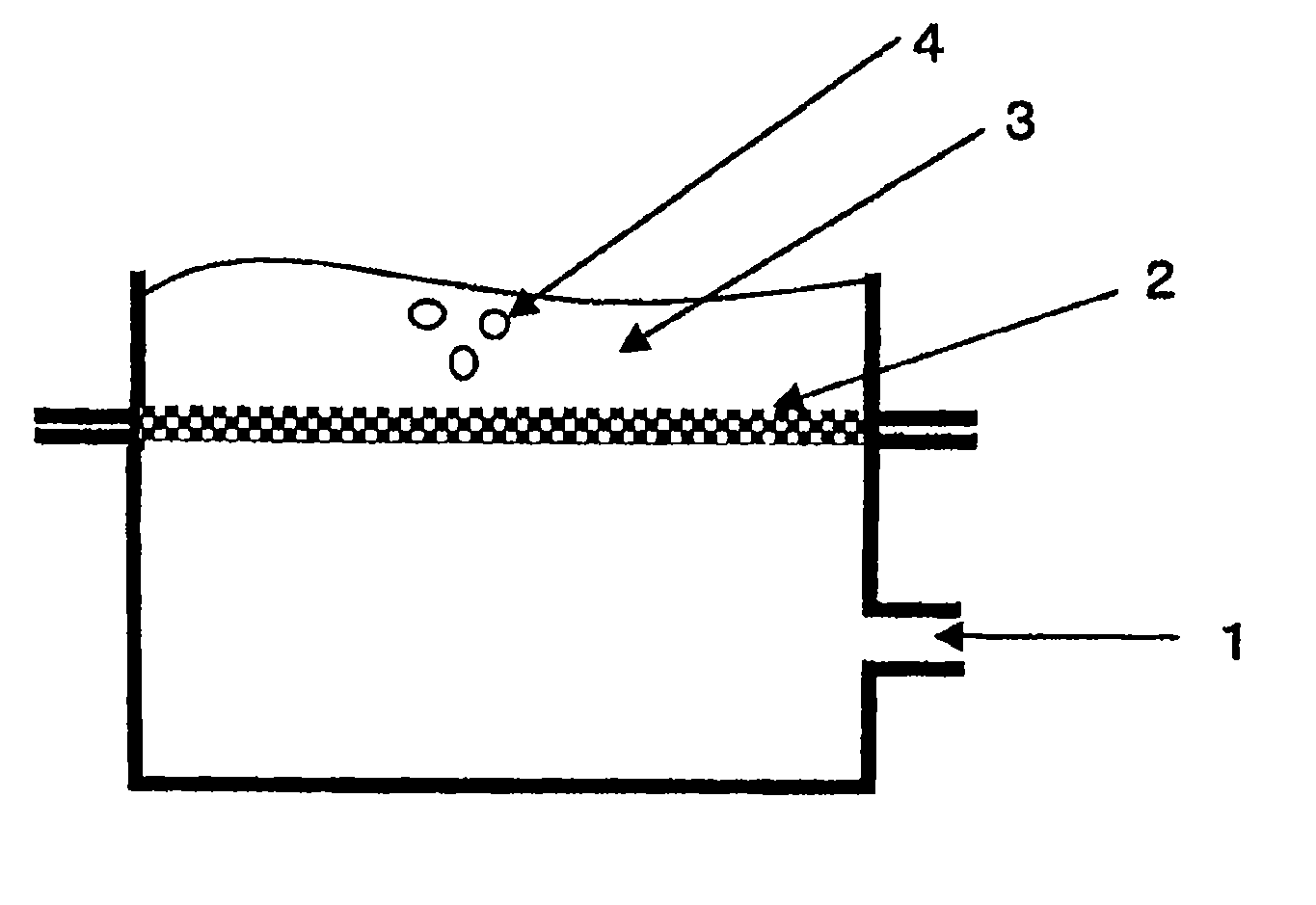
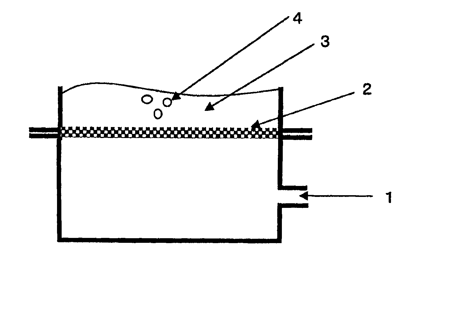
[0035]Polyvinyl alcohol having a degree of saponification of 87.0 to 89.0 mol % was dissolved in water to prepare a polymer solution (aqueous spinning solution) having a solid concentration of 20 mass %. As shown in FIG. 1, this polymer solution 3 was put in an 80-mm diameter stainless steel cylindrical container, and an unwoven fabric 2 (unwoven fabric from Hirose Seishi Kabushiki Kaisha; brand name, 15TH145) was placed as a porous material for bubble formation so that compressed air 1 could be supplied from the bottom surface. Compressed air having a pressure of 4.0 kPa was supplied through the unwoven fabric 2 to continuously form bubbles 4 on the whole surface of the polymer solution. As the counter electrode, an aluminum foil was placed 8 cm away from the bubble surface (not shown). Once bubbles have been formed uniformly on the polymer solution, a high DC voltage of 40 kV was applied to the polymer solution side to form a microfiber agglomerate on the aluminum foil. Electrospi...

examples 2 to 8

[0036]Under the conditions shown in Table 1, the concentration of polyvinyl alcohol having a degree of saponification of 87.0 to 89.0 mol % was prepared, and the porous material for bubble formation and the compressed air pressure were varied. Spinning was performed as in Example 1, and the spun fibers of the microfiber agglomerates were weighed. Results are shown in Table 1. It was found that as the compressed air pressure increased, the weight of the spun fibers increased.

examples 9 to 10

[0037]Poly-ε-caprolactone having a weight-average molecular weight of 80,000 was dissolved in acetone to prepare a polymer solution having a solid concentration of 5 mass %. The porous material for bubble formation and the compressed air pressure were varied as shown in Table 1, and then spinning was performed as in Example 1, and the spun fibers of the microfiber agglomerates were weighed. Results are shown in Table 1. It was found that as the compressed air pressure increased, the weight of the spun fibers increased.


PUM

PropertyMeasurementUnit
diameteraaaaaaaaaa
diameteraaaaaaaaaa
voltageaaaaaaaaaa

Abstract

A process for producing a fiber assembly or agglomerate requiring micropores, such as for a battery separator or any of various filters, which is performed by electrostatic spinning and provides high productivity and ease of maintenance, is provided. The process for producing a microfiber assembly or agglomerate by electrostatic spinning includes continuously forming bubbles on a polymer solution or a polymer melt and applying high voltage to the formed bubbles. The bubbles can be formed by passing compressed air through porous material of one or a combination of two or more of plastic, ceramic and metal materials, or capillaries.

Description

CROSS REFERENCE TO RELATED APPLICATIONS[0001]This application is a national stage filing under section 371 of International Application No. PCT / JP2006 / 323922, filed on Nov. 30, 2006 and published in Japanese on Jan. 24, 2008, as WO 2008 / 010307, and which claims priority of Japanese application No. JP 2006-199179, filed on Jul. 21, 2006, the entire disclosure of these applications being hereby incorporated herein by reference.TECHNICAL FIELD[0002]The present invention relates to a process for producing microfiber assembly or agglomerate by electrostatic spinning or electrospinning that provides high productivity and ease of maintenance.BACKGROUND ART[0003]Fiber assemblies and agglomerates, typically nonwoven fabrics and the like, have been applied to such as battery separators and filters, making good use of the micropores. The requirements for the size of the micropores vary depending upon the fields where they are applied to. For example, nickel metal hydride battery separators req...

Claims


Application Information

Patent Timeline
Patent Type & Authority Applications(United States)
IPC IPC(8): B29C47/00D01D5/04D04H1/728
CPCD01D5/0069D04H1/728D04H1/42D04H1/43838D01D5/00D04H3/16
Inventor KISHIMOTO, YOSHINORI
Owner KANKYOKIKI CORP
Why Eureka
Try Eureka