Radial flux permanent magnet alternator with dielectric stator block

a permanent magnet alternator and dielectric technology, applied in the direction of machines/engines, magnetic circuits characterised by magnetic materials, electric generator control, etc., can solve the problems of reducing net power output, unable to identify and account, prior art dynamos suffering from non-mechanical sources of rotational resistance, etc., and achieve high operation and maintenance costs.

Active Publication Date: 2011-11-17
LEIDOS
View PDF7 Cites 11 Cited by
  • Summary
  • Abstract
  • Description
  • Claims
  • Application Information

AI Technical Summary

Benefits of technology

[0005]These existing power generation systems used to, for example, power individual buoys, fail to identify and account for significant sources of resistance which decrease net power output. More specifically, prior art dynamos suffer from non-mechanical sources of rotational resistance arising from the interaction of the moving permanent magnets with ferrous, metallic, or otherwise conductive components of the generator. These sources of resistance include, generally: “cogging,” which is caused by attraction between the permanent magnets and the ferrous cores at the center of the stator's coils and Eddy currents which form in conductive materials and create a tangible mechanical resistance and “leak” energy as they flow through the conductive materials (typically aluminum or steel) in structural components, most notably the generator housing. The two forces are amplified by the step-up ratio between the original moving source (usually a rotating shaft) and the required working speed of the generator to achieve a useable electrical output voltage and current (according to Faraday's Law). The requirement for mechanical step-up, e.g., some form of transmission, is a source of initial cost and the primary source of unscheduled maintenance, which itself is a major cost element for remote applications. Further, many buoys currently rely on solar panels and / or primary and secondary batteries for operational power and often operate at a net power deficit. This results in the need for more frequent maintenance visits and high operation and maintenance costs.

Problems solved by technology

These existing power generation systems used to, for example, power individual buoys, fail to identify and account for significant sources of resistance which decrease net power output.
More specifically, prior art dynamos suffer from non-mechanical sources of rotational resistance arising from the interaction of the moving permanent magnets with ferrous, metallic, or otherwise conductive components of the generator.
The requirement for mechanical step-up, e.g., some form of transmission, is a source of initial cost and the primary source of unscheduled maintenance, which itself is a major cost element for remote applications.
Further, many buoys currently rely on solar panels and / or primary and secondary batteries for operational power and often operate at a net power deficit.
This results in the need for more frequent maintenance visits and high operation and maintenance costs.

Method used


Image

  • Radial flux permanent magnet alternator with dielectric stator block
  • Radial flux permanent magnet alternator with dielectric stator block
  • Radial flux permanent magnet alternator with dielectric stator block

Examples


Embodiment Construction

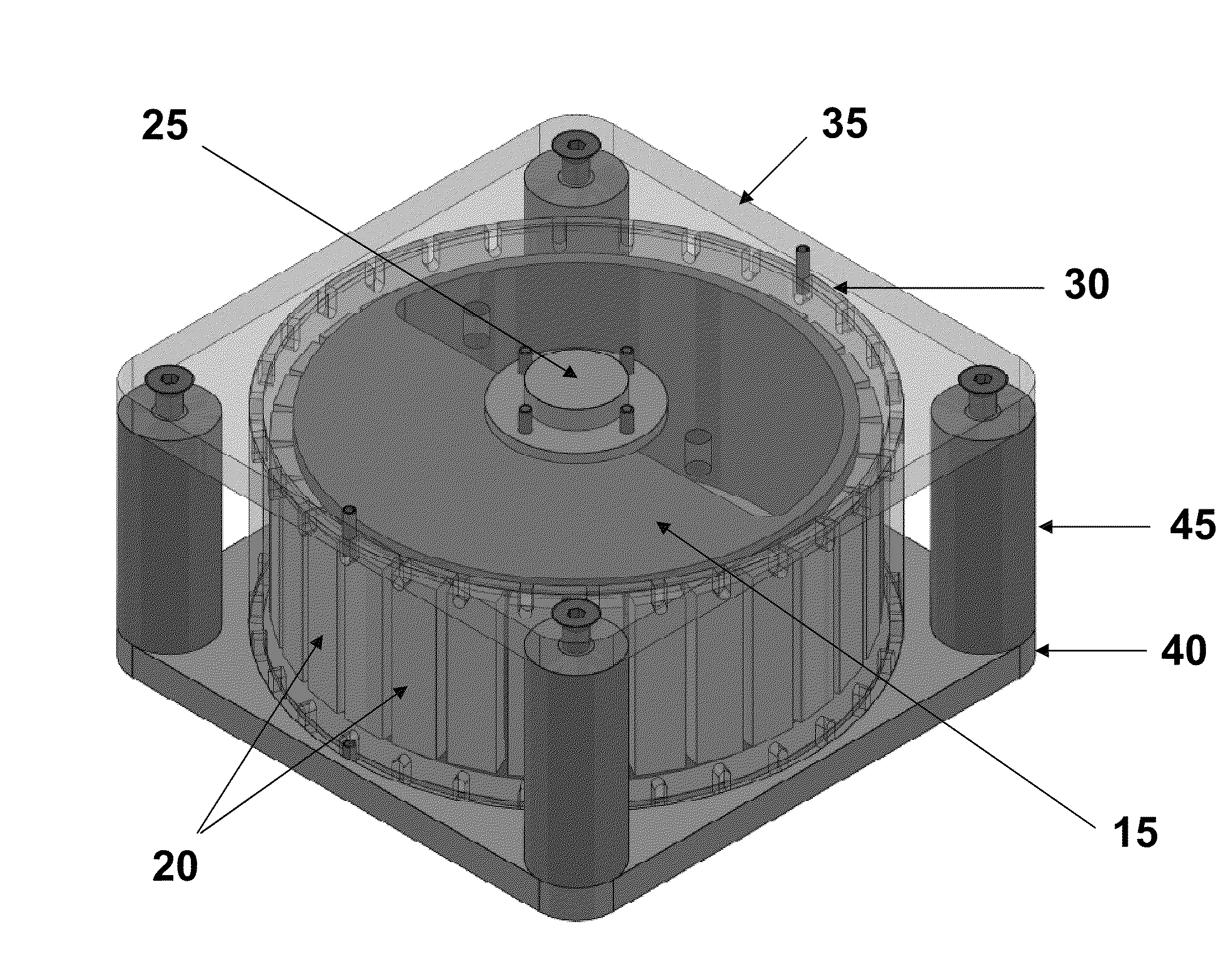
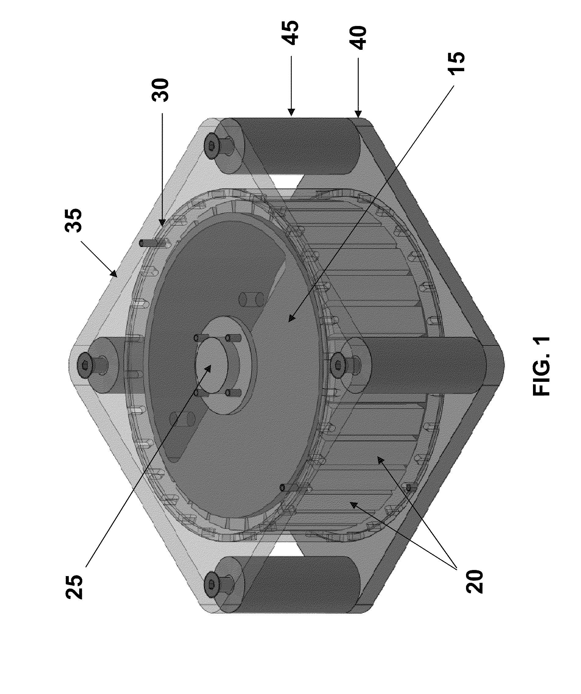
[0018]In an exemplary embodiment of the present invention, an energy conversion system 10 in a radial flux configuration as shown in FIG. 1 includes at least the following components: a rotor assembly including rotor 15, magnets 20, shaft 25; stator 30; upper plate 35 (optional); lower plate 40 (optional) and spacers 45 (optional). Each of these components is described in more detail herein.

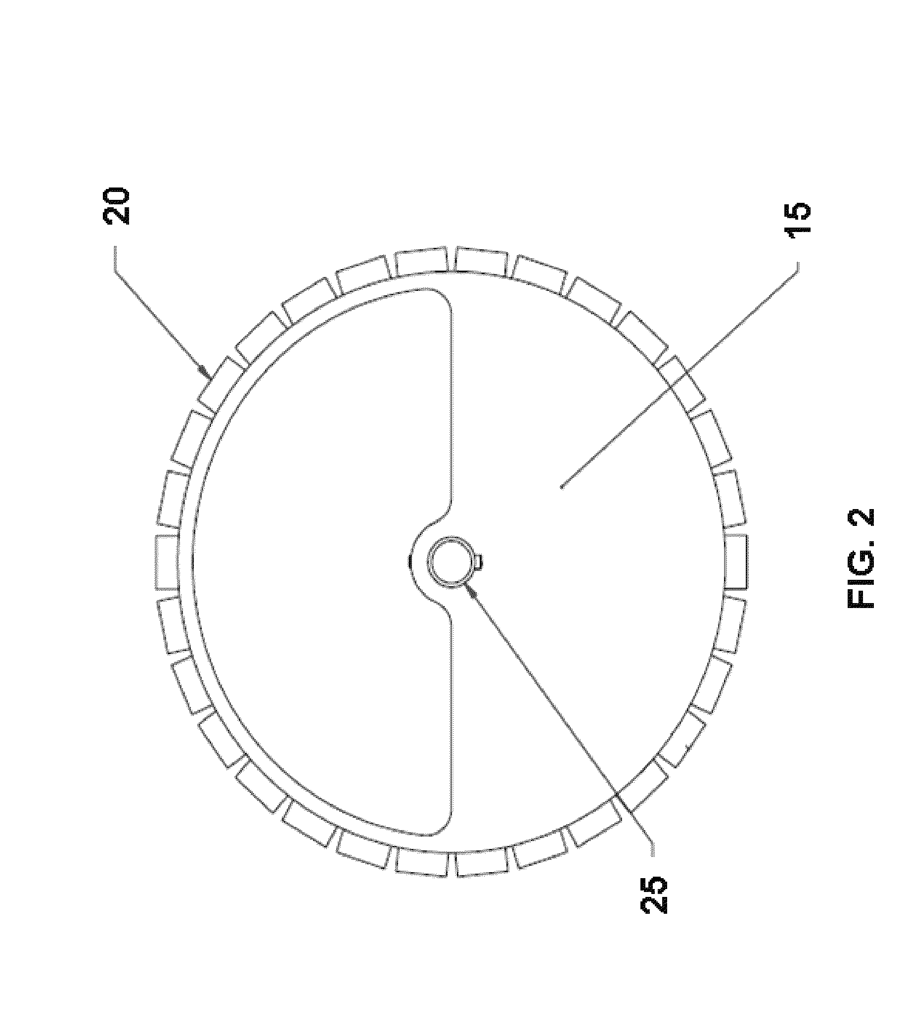
[0019]The energy conversion system 10 is based on the use of permanent magnets in what is known as a radial flux configuration. The configuration is brushless and results in much greater swept coil area in the same footprint as an axial-flux design and is well suited to low rotational speed applications as low as approximately 1 rpm. FIGS. 2 through 4 illustrate top, front and cross-sectional views of the rotor assembly which includes rotor 15, permanent magnets 20 and shaft 25. In a particular embodiment, there are 30 neodymium magnets 20 affixed to the outside of cylindrical steel rotor 15 with...


PUM


Abstract

An energy conversion system is described and includes a cylindrical rotor having a mass and multiple magnets affixed on an outer face thereof; a cylindrical stator including a dielectric cylinder wound with copper wire in a predetermined configuration, the cylindrical rotor being placed within the cylindrical stator; and a rotatable shaft for rotating the rotor, the rotatable shaft being placed in the center of the cylindrical rotor. The system harvests environmental energy for lower power generation and accounts for non-mechanical sources of rotational resistance within the generator.

Description

BACKGROUND OF THE INVENTION[0001]1. Field of the Invention[0002]Efficient dynamo-based production of electrical power in environmental energy harvesting and other applications in which the dynamo rotor is driven at low and variable revolutions per minute. Specific applications include powering systems aboard unmanned maritime platforms and wind power generation.[0003]2. Description of the Related Art[0004]Extraction of useful energy from locally available environmental sources is becoming vitally important to a wide range of applications, and immediately so for remote sensing and communications devices for military and civilian uses. A common element in all devices that harvest environmental energy from kinetic sources such as moving wind or water is the electrical dynamo, which must be capable of operating without an external source of current and therefore typically utilizes permanent magnets. Numerous electrical dynamo designs exist and are patented. In particular, these designs ...

Claims


Application Information

Patent Timeline
Patent Type & Authority Applications(United States)
IPC IPC(8): F03B13/14H02K11/04F03B13/00H02K1/02
CPCH02K3/47Y02E10/38H02K21/14Y02E10/30
Inventor HENCH, STEVEN C.FRALICK, CHARLES R.
Owner LEIDOS
Why Eureka
Try Eureka