Drawer locking apparatus of a cabinet
a locking apparatus and drawer technology, applied in the direction of building locks, construction, construction fastening devices, etc., can solve the problems of inconvenient and troublesome to perform the locking operation of the drawer, and the cost of manufacturing time and labor and the cost of the material of such structure are relatively high, so as to facilitate assembly and facilitate the locking effect, the cost of the materials of the components is lower, and the effect of convenient and convenient locking
- Summary
- Abstract
- Description
- Claims
- Application Information
AI Technical Summary
Benefits of technology
Problems solved by technology
Method used
Image
Examples
second embodiment
[0033] Referring to FIGS. 6 to 8 and FIG. 6A, the force application section 72 is a rod body with a certain length. The rod body passes through the transmission section 74. One end of the rod body is pivotally connected with the rear panel of the cabinet body 11 corresponding to rear side of the drawer 12. The other end of the rod body is pivotally connected with the cabinet body 11 corresponding to front side of the drawer 12 and exposed to outer side of the cabinet body 11. The other end of the rod body is equipped with a key-driven unit. The rod body has a bent section 721 for abutting against the transmission section 74. The two end points of the rod body and the contact point of the rod body in contact with the transmission section 74 are not collinear. By means of turning the key-driven unit, the transmission section 74 can be driven to drive the slide section 14 to slide between the first and second positions.
[0034] The transmission section 74 is formed with a polygonal hole...
third embodiment
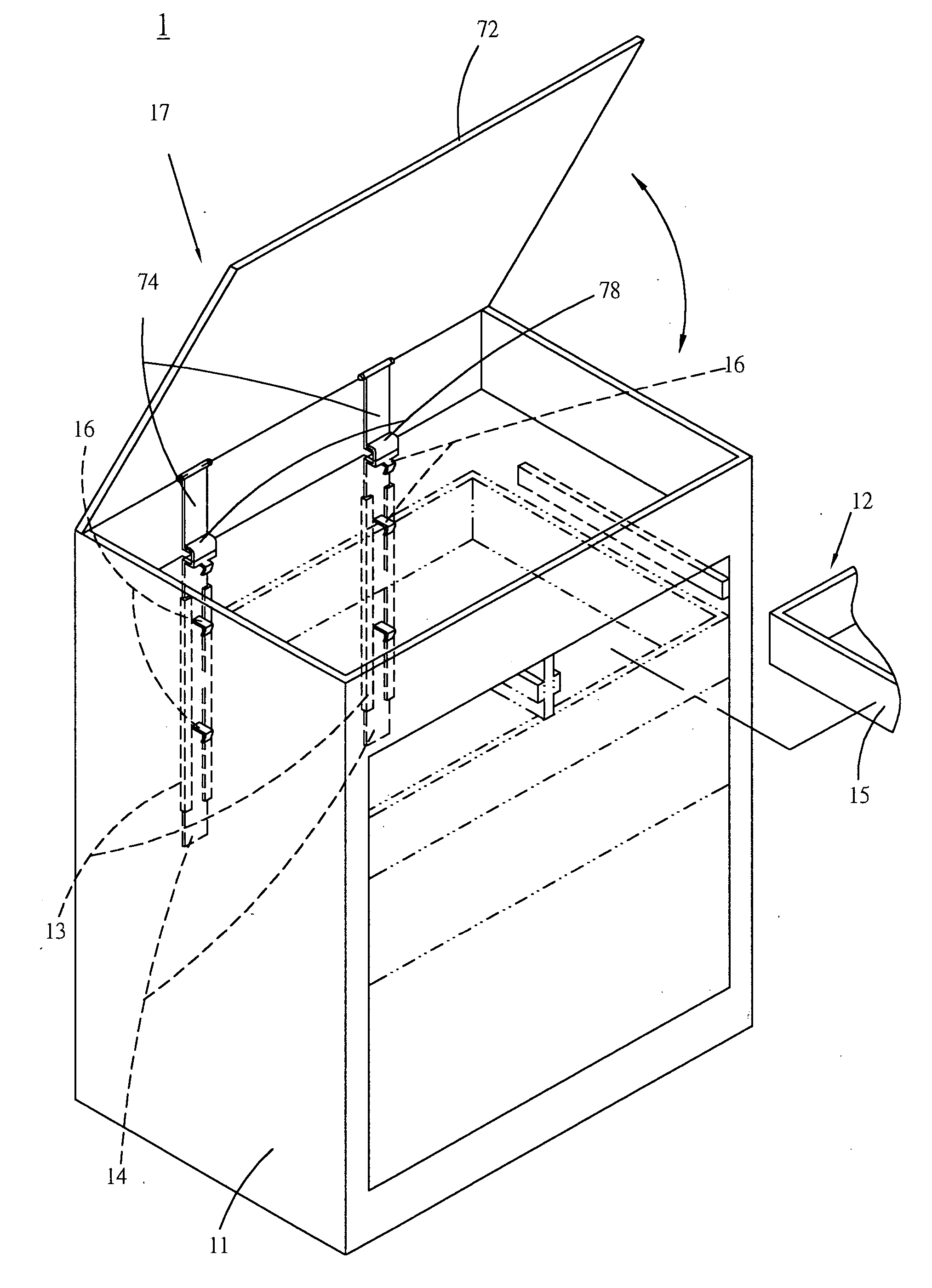
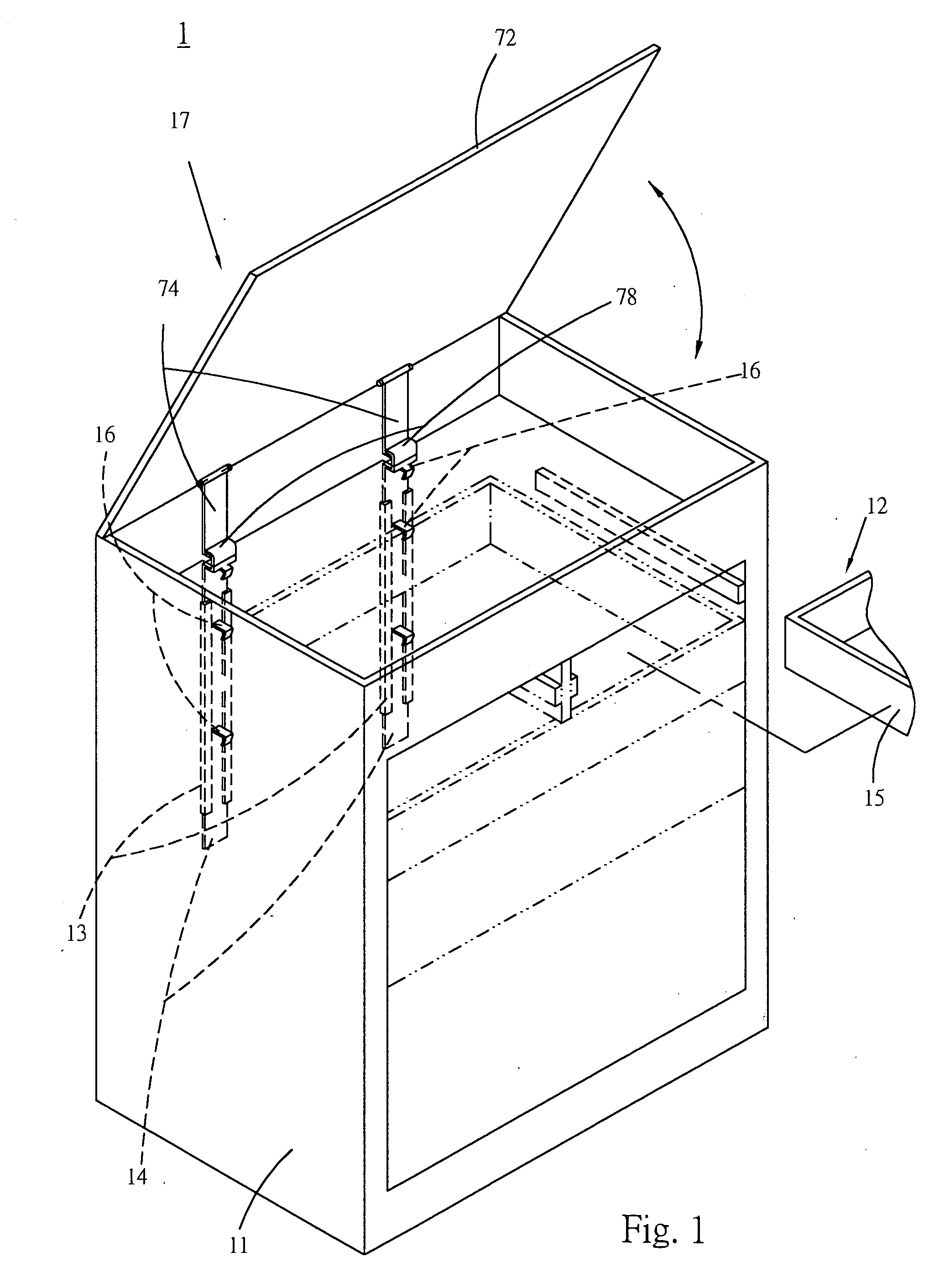
[0035]FIGS. 9 and 10 show the present invention, in which the force application section 72 includes a resilient member 72′ and a cover board 72″. The resilient member 72′ can be a coiled spring disposed at the middle of the transmission section 74 for driving the same.
[0036] One side of the cover board 72″ is pivotally connected with one side of the panel of the cabinet body 11, on which the base seat 13 is mounted. The cover board 72″ is positioned on upper side of the cabinet body 11 to abut against upper end of the transmission section 74 or release the upper end of the transmission section 74. When the cover board 72″ is pivoted up and opened, the transmission section 74 is released from the abutting force of the cover board 72″. The resilient member 72′ pushes the transmission section 74 to move upward or the resilient member 72′ pushes the transmission section 74 to move upward and still abut against the cover board 72″, whereby the slide section 14 is positioned in the first ...
PUM
 Abstract
Description
Claims
Application Information
 - R&D
- Intellectual Property
- Life Sciences
- Materials
- Tech Scout
- Unparalleled Data Quality
- Higher Quality Content
- 60% Fewer Hallucinations
Browse by: Latest US Patents, China's latest patents, Technical Efficacy Thesaurus, Application Domain, Technology Topic, Popular Technical Reports.
© 2025 PatSnap. All rights reserved.Legal|Privacy policy|Modern Slavery Act Transparency Statement|Sitemap|About US| Contact US: help@patsnap.com


