
Apparatus and method for detecting lens thickness

a technology of ophthalmology and lens thickness, which is applied in the direction of optical apparatus testing, instruments, structural/machine measurement, etc., can solve the problems of insufficient and/or destructive metal-based systems designed to characterize the geometry of ophthalmology, inaccurate measurement, and high labor intensity

Active Publication Date: 2006-06-22
ALCON INC
View PDF2 Cites 27 Cited by
  • Summary
  • Abstract
  • Description
  • Claims
  • Application Information

AI Technical Summary

Benefits of technology

[0008] In one embodiment the rotating fixture may include a seal and a bearing that are connected to the measurement chamber via the adapter. In another embodiment, a magnetic coupling may be used to connect the rotating fixture to the measurement chamber. In one embodiment of the current invention, a vacuum line may be used in fluid connection with the seat. In a related embodiment, the seat may be made of porous metal. In another embodiment of the present invention, the measurement chamber may have one or more windows.
[0009] The present invention may also include a method for measuring the thickness of an ophthalmic lens and may include the steps of taking one sets of images and subtracting the first image from the second image to obtain a thickness measurement, where taking one set of images comprises taking a first image of the measurement seat, placing a sample lens on the sample seat, and taking a second image if the sample lens on the measurement seat. In another embodiment, the method may include providing a measurement chamber and / or a rotating fixture. In still another embodiment, more than one set of images may be taken. In a related embodiment, the method may include transforming the images into numerical data, analyzing the data, and / or archiving the data.

Problems solved by technology

Most metrology systems designed to characterize the geometry of a lens are incomplete and / or destructive (or both).
Besides the obvious problem of destroying the lens, this process is extremely labor intensive and only results in capturing one or two “slices” through the lens.
Additionally, most types of contact lenses tend to exhibit shrinkage when removed from a hydrated environment, making measurement inaccurate.
This method may be very slow and involves correcting for squash factors when the lens is compressed by the probe.
Additionally, current methods of measuring or inspecting the base curve of a lens are very difficult.

Method used


Image

  • Apparatus and method for detecting lens thickness
  • Apparatus and method for detecting lens thickness
  • Apparatus and method for detecting lens thickness

Examples


Embodiment Construction

[0022] Reference now will be made in detail to the embodiments of the invention. It will be apparent to those skilled in the art that various modifications and variations can be made in the present invention without departing from the scope or spirit of the invention. For instance, features illustrated or described as part of one embodiment, can be used on another embodiment to yield a still further embodiment. Thus, it is intended that the present invention cover such modifications and variations as come within the scope of the appended claims and their equivalents. Other objects, features and aspects of the present invention are disclosed in or are obvious from the following detailed description. It is to be understood by one of ordinary skill in the art that the present discussion is a description of exemplary embodiments only, and is not intended as limiting the broader aspects of the present invention.

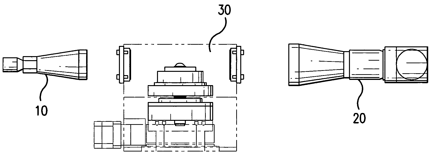
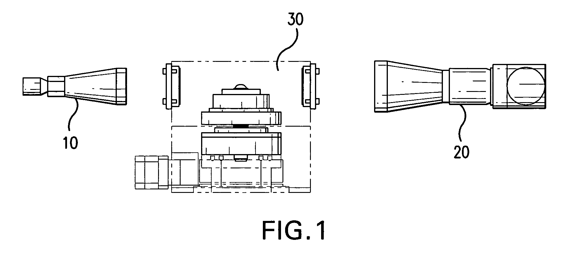
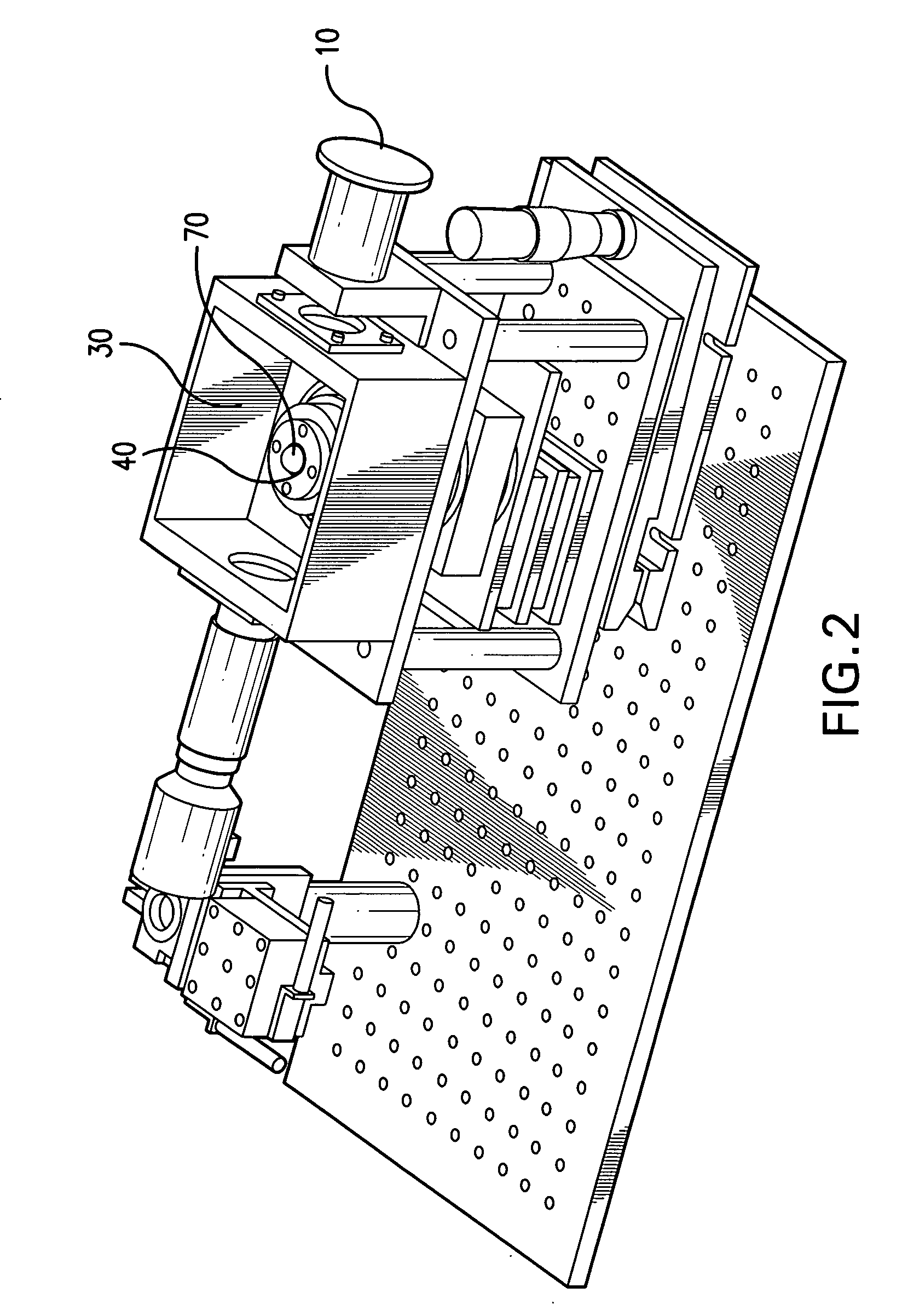
[0023] The present invention is an apparatus and method to measure the thick...


PUM

PropertyMeasurementUnit
pore sizeaaaaaaaaaa
pressure dropaaaaaaaaaa
distanceaaaaaaaaaa

Abstract

The present invention relates to a non-contact / non-destructive method and apparatus for measuring the thickness of an ophthalmic lens. The present invention also provides a method for inspecting or measuring the base curve of a lens.

Description

[0001] This application claims the benefit under 35 USC § 119 (e) of U.S. provisional application No. 60 / 638,635 filed Dec. 22, 2004, incorporated by reference in its entirety.FIELD OF THE INVENTION [0002] The present invention relates to a non-contact / non-destructive method and apparatus for measuring the thickness of an ophthalmic lens. The present invention also provides a method for inspecting or measuring the base curve of a lens. BACKGROUND OF THE INVENTION [0003] Most metrology systems designed to characterize the geometry of a lens are incomplete and / or destructive (or both). Currently, to find the thickness of a lens, the lens must be cut into one or more thin slices and measured under a microscope. Besides the obvious problem of destroying the lens, this process is extremely labor intensive and only results in capturing one or two “slices” through the lens. Currently, only 5-10 points can be measured per slice because of the time and skill required. Additionally, most type...

Claims


Application Information

Patent Timeline
Patent Type & Authority Applications(United States)
IPC IPC(8): G01B9/00G01N21/01
CPCG01M11/02G01M11/0207G01M11/0214
Inventor HALL, WILLIAM JORDAN
Owner ALCON INC
Learn More