

Frame forwarding device and method for staying loop of frame
a frame and loop technology, applied in the field of frame forwarding devices, can solve the problems of data loops and no means for staying loops of data, and achieve the effect of efficiently staying loops generated in layer 2 networks
- Summary
- Abstract
- Description
- Claims
- Application Information
AI Technical Summary
Benefits of technology
Problems solved by technology
Method used
Image

Examples
operation example 1
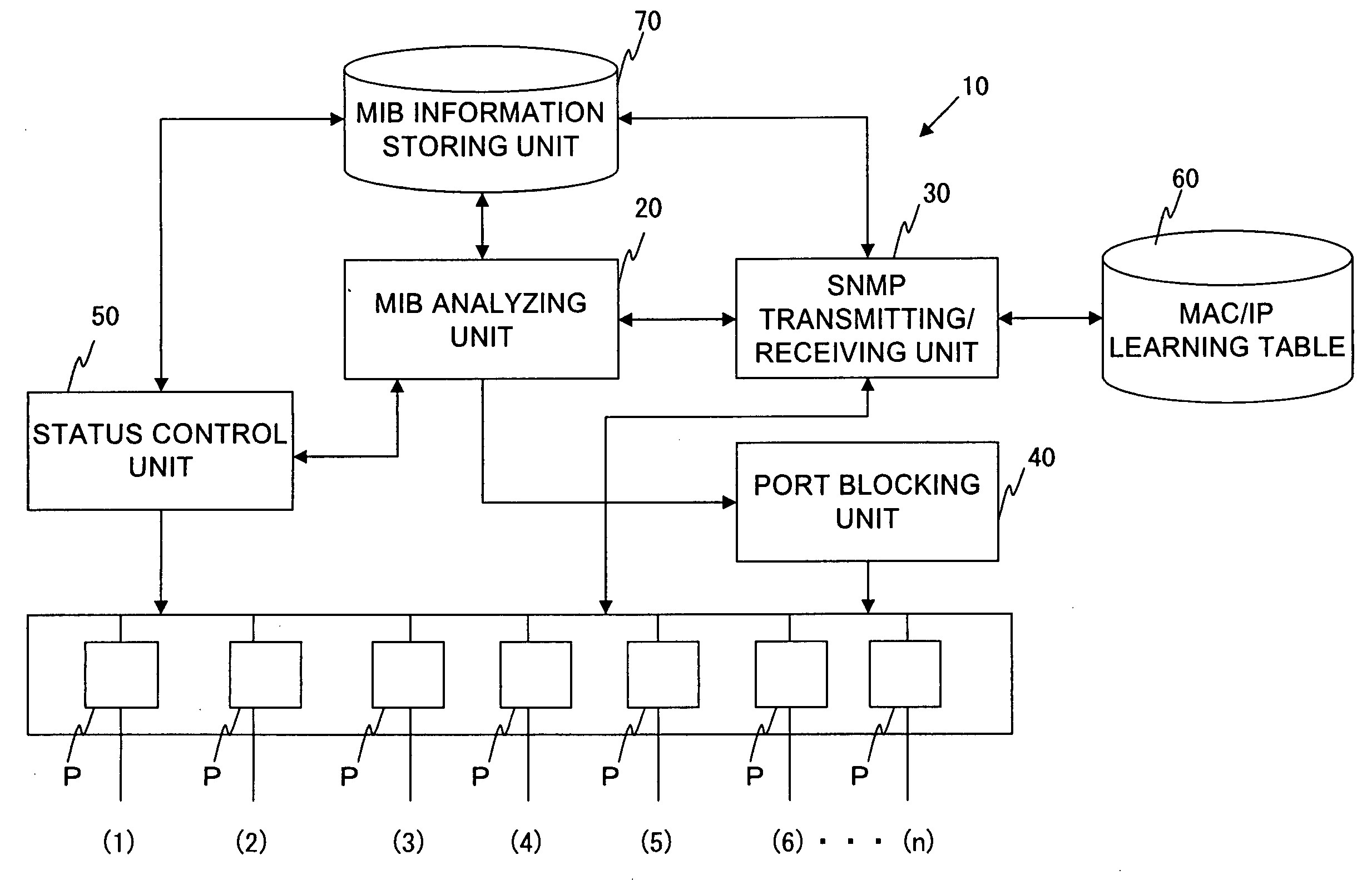
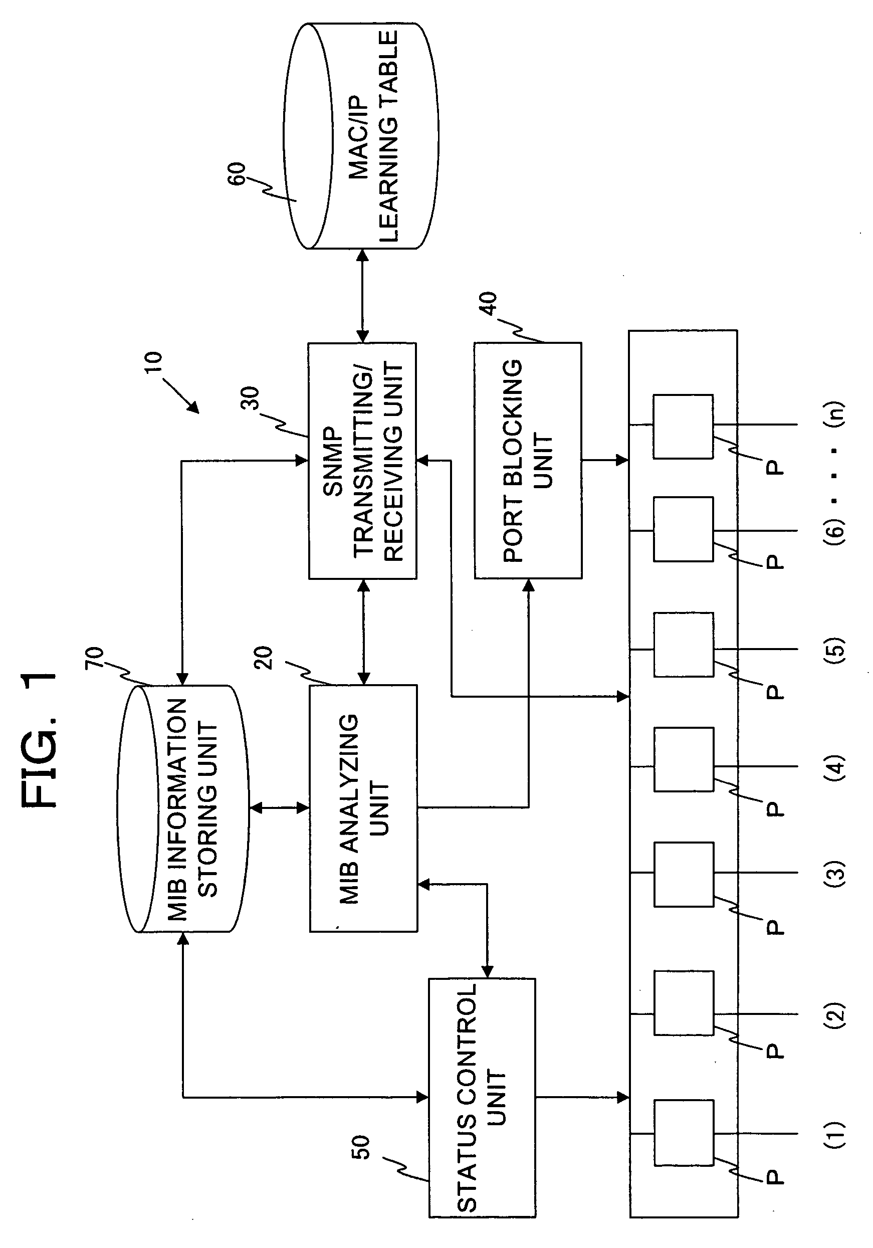
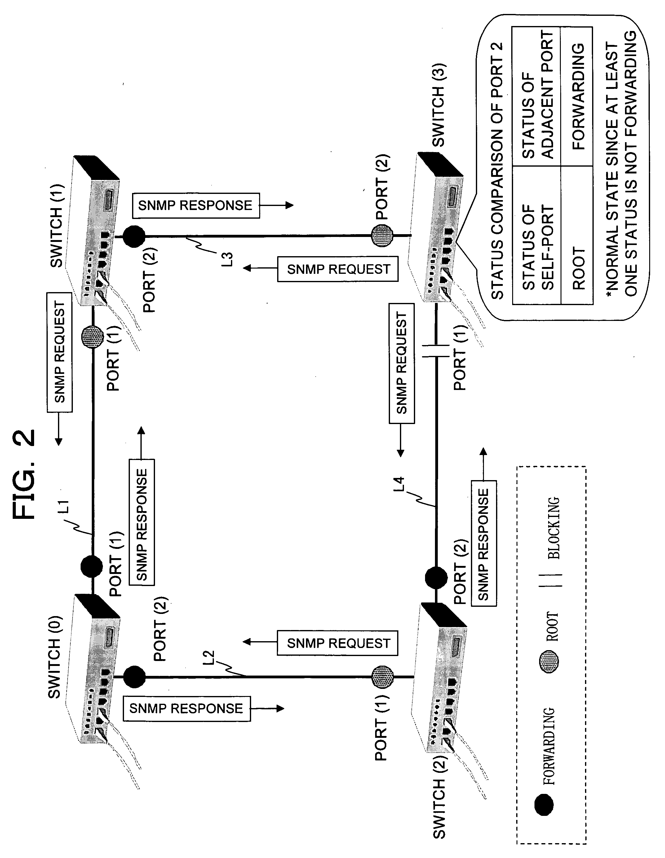
[0056] Next, an operation example in a network to which the layer 2 switch shown in FIG. 1 is applied will be described. FIGS. 2 and 3 are views illustrating Operation Example 1. FIG. 2 shows the operation of each of layer 2 switches when a failure does not occur in each of the layer 2 switches and the link connecting the switches (normal state). FIG. 3 shows the operation when a failure occurs in one layer 2 switch.
[0057]FIG. 2 shows the layer 2 network (Ethernet (Registered Trademark)) based on the IEEE (Institute of Electrical and Electronic Engineers) 802.3 in which switches (0), (1), (2), and (3) are connected. Each of the switches (0) to (3) has a configuration of the layer 2 switch shown in FIG. 1. The switch (0) is connected to the switches (1) and (2) via links L1 and L2. Furthermore, the switch (1) is connected to the switch (3) via the link L3, and the switch (3) is connected to the switch (2) via the link L4.
[0058] Each of the switches (0) and (1) respectively contains...
operation example 2
[0079] Next, Operation Example 2 will be described with reference to FIGS. 2 and 4. As shown in FIG. 2, an SNMP request is configured so as to be transmitted from a switch (switch in which a port status is “Root” or “Blocking”) on a downstream side with respect to the flow of data to an adjacent switch (switch in which a port status is “Forwarding”) on an upstream side. Furthermore, the BPDU by the STP is transmitted from the switch on the upstream side of the data to the switch on the downstream side. As shown in FIG. 2, since the port status of the port (1) of the switch (3) is “Blocking,” the SNMP request is configured so as to be transmitted with respect to the switch (2).
[0080] Herein, as shown in FIG. 4, the case is considerable in which a failure occurs in the switch (3), and the switch (3) cannot transmit an SNMP request with respect to the switch (2). In this case, the switch (3) cannot acquire the port status of the corresponding port (2) from the adjacent switch (2) by t...
operation example 3
[0087] Next, Operation Example 3 in the network system shown in FIG. 2 will be described. FIGS. 5 and 6 are views illustrating Operation Example 3. In Operation Example 1, a switch positioned on a downstream side with respect to the data flow transmits an SNMP request to an adjacent switch on an upstream side. While in Operation Example 2, when an SNMP request does not arrive any more from the adjacent switch on the downstream side, the switch on the upstream side transmits an SNMP request to the adjacent switch on the downstream side.
[0088] As shown in FIG. 5, in Operation Example 3, each of switches (0) to (3) transmits periodically an SNMP request to the adjacent switch, with respect to each port P containing a link connecting to the adjacent switch, irrespective of whether or not the self-switch is upstream or downstream with respect to the data flow.
[0089] More specifically, the MIB analyzing unit 20 of the respective switches (0) to (3) instructs the SNMP transmitting / receiv...
PUM
 Abstract
Description
Claims
Application Information