
Hot-film air mass meter having frequency-modulated signal detection

a frequency-modulated signal and air mass meter technology, which is applied in the direction of volume/mass flow measurement, measurement devices, instruments, etc., can solve the problems of oil contamination, contamination of sensor types, and falsification of measuring signals, etc., to reduce the area minimally required, reduce interference effects, and small and space-saving design

Inactive Publication Date: 2009-12-24
ROBERT BOSCH GMBH
View PDF5 Cites 12 Cited by
  • Summary
  • Abstract
  • Description
  • Claims
  • Application Information

AI Technical Summary

Benefits of technology

[0010]The hot-film air mass meter has a sensor chip having a chip surface across which an air mass flow is able to flow. A “main flow direction” may be understood to denote, e.g., a main transportation direction of the air mass flow at the location of the hot-film air mass meter, e.g., at the location of a sensor chip. Local turbulence may be disregarded for the most part. The hot-film air mass meter is optimized especially for measuring an air mass flow having a flow velocity of between 0 and 60 m / s. As described above, the sensor chip may be, e.g., a silicon chip. The chip surface in turn has a measuring surface and a mainland surface. In this context, the subdivision of the chip surface should be implemented in such a way, in particular, that the sensor chip has a transversal conductivity in the region of the measuring surface that is less by at least one order of magnitude than in the region of the mainland surface. This reduction in the transversal conductivity may be achieved in different ways. As known from the related art and described earlier, it is possible to use sensor chips having a sensor diaphragm with a thickness of only a few μm, for instance. The low thermal conductivity (approx. 0.02 W / m K) of the air surrounding the sensor diaphragm is utilized in this context. As an alternative, a porous region or a plurality of porous regions in the sensor chip may be realized as measuring region having a measuring surface that faces the air mass flow, for instance by rendering a silicon chip porous. This enables the production of measuring regions which, due to the enclosed air cavities, have transversal conductivities of 0.1 to 2 W / m K, in comparison with a silicon substrate having a thermal conductivity of approximately 156 W / m K.
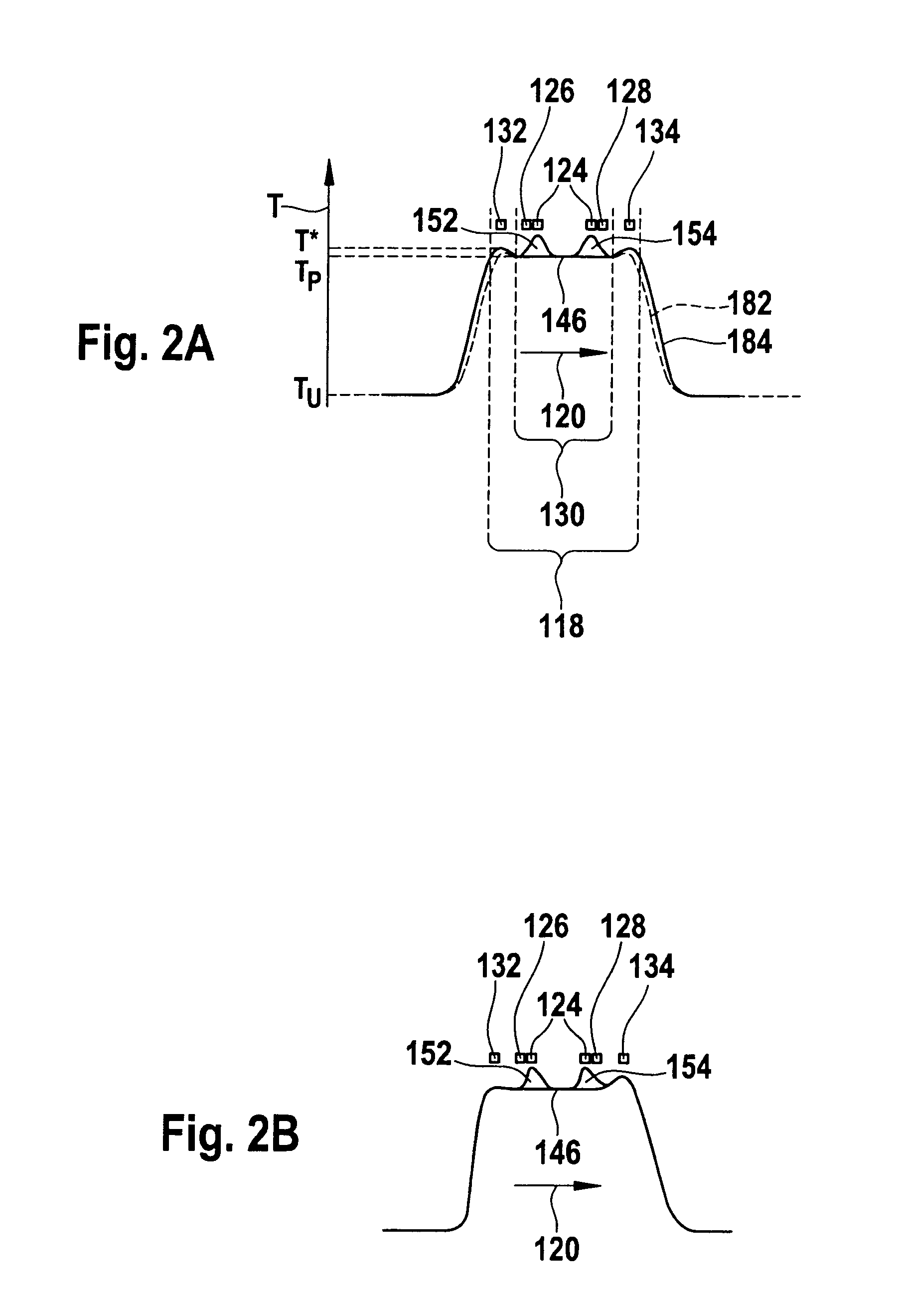
[0015]The fact that the temperature increase caused by the periodic heating does not extend into the edge region of the measuring surface, or extends only to a negligible extent, has two decisive advantages: For one, the temperature profile of the periodic heating used for measuring the air mass flow does not superimpose itself, or superimposes itself only slightly, to air turbulence that arises in the edge region of the measuring surface and is due to contamination deposits that have collected there, which typically have an extension of approximately 100 μm parallel to the main flow direction (i.e., into the region of the measuring surface). For the most part, the actual measurement thus actually detects the main flow of the air mass flow, without any significant influence by turbulence attributable to contamination. For another, the temperature profile of the periodic heating used to measure the air mass flow is not, or only insignificantly, affected by changes in the thermal conductivity of the measuring surface in the edge region of the measuring surface, such changes likewise being caused by the contamination arising there. Both from the standpoint of flow mechanics and thermal aspects, the heating by the at least one central heating element is thus largely decoupled from the interference by contamination present in the edge region of the measuring surface.
[0024]However, the disadvantage of a precisely level “plateau” is that contamination arising in the region of this plateau is no longer subjected to any thermo-gradient force and is therefore not shifted out of this region. It has therefore shown to be advantageous if a slight temperature gradient (e.g., 10 K / 100 μm) still remains in the region of this “plateau” as well, which shifts contamination into the edge region of the measuring surface. Stronger temperature gradients may then adjoin the plateau region in the edge region of the measuring surface so as to effectively keep contamination away from the plateau.
[0026]This selection of the basic temperature on the basis of an “over-temperature” relative to the ambient temperature has numerous advantages. For instance, it minimizes interference effects caused by fluctuations in the ambient temperature. A main advantage, however, consists of the “barrier effect” described previously already. A “temperature wall” is built around the central hot-film air mass meter circuit, which, due to the thermo-gradient effect, prevents contamination such as oil, in particular, from reaching the region of the hot-film air mass meter circuit. This design of the hot-film air mass meter and the described method thus effectively protects the central hot-film air mass meter circuit from interference effects.
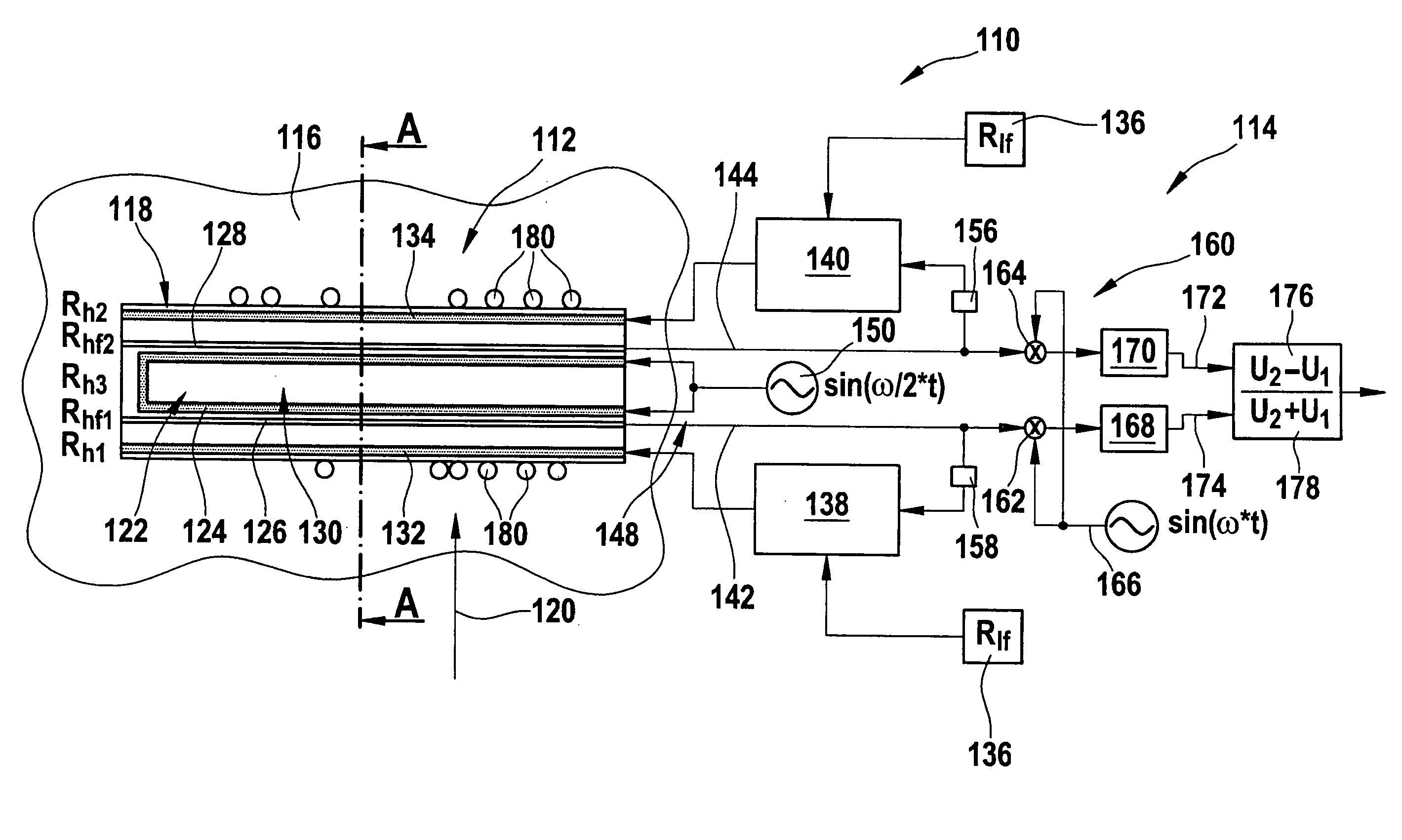
[0027]In addition to the advantages already described, the described hot-film air mass meter and the described method in one of the described developments have numerous additional advantages in comparison with conventional devices and methods. In particular, no absolute values of the temperature profile but only relative changes within a separately controlled temperature plateau are detected. Contamination deposits outside this area therefore do not affect the measuring signal. Furthermore, by scaling the output signal to the sum of the input voltages (composite signal), the hot-film air mass meter is able to be designed to be immune to resistance drift of the circuit tracks. Another advantage is that the sensor chip of the hot-film air mass meter may have a relatively small and space-saving design. This makes it possible to considerably reduce the area minimally required for the measurement, i.e., the measuring surface or the sensor region, for instance, in comparison with the related art. This is especially due to the fact that, as described earlier, a “temperature wall” is able to be built around the measuring surface or around the sensor region due to the essentially constant basic temperature profile, so that even contamination located in close proximity to the circuit tracks of the central hot-film air mass meter circuit is effectively able to be kept away from the central hot-film air mass meter circuit.

Problems solved by technology

One problem with such a type of sensor known from DE 101 11 840 C2, for instance, is that contamination of the sensor type can often occur, such as contamination by oil, other fluids, or other types of soiling.
This oil deposit can lead to an undesired effect on the measuring signal of the sensor chip, especially since an oil film on the surface of the sensor chip affects the thermal conductivity of the surface, which results in a falsification of the measuring signals.
Furthermore, the oil contamination can also occur during or shortly after deactivation of the internal combustion engine, e.g., a diesel engine.
This supplementary heater is heated electrically, in such a way that thermo-gradient turbulence occurs in the region of the supplementary heater, which results in deposits of the contamination of the flowing medium in the region of the supplementary heater, beyond the area of the sensor region.
In practice, however, the system disclosed in DE 101 11 840 C2 and the disclosed method have disadvantages in different operating modes of the internal combustion engine.
For instance, one disadvantage is that a localization of the thermo-gradient turbulence as intended by the device disclosed in DE 101 11 840 C2 is virtually impossible in practice.
Due to the high thermal conductivity of the silicon, the heat generated by the supplementary heater easily moves across the entire chip, which results in a “smeared” temperature distribution and thus to heating of the entire chip.
The problem of contamination of the diaphragm or the sensor surface is made worse by thermodynamic effects.
This fluid wall may be fully or partially carried along by the air flow, so that oil droplets end up on the sensor diaphragm and may affect the measurement there.
Furthermore, the fluid wall causes an increase in the thermal conductivity at the edge of the sensor diaphragm, which may lead to falsification and drift of the measuring signal.

Method used


Image

  • Hot-film air mass meter having frequency-modulated signal detection
  • Hot-film air mass meter having frequency-modulated signal detection
  • Hot-film air mass meter having frequency-modulated signal detection

Examples


Embodiment Construction

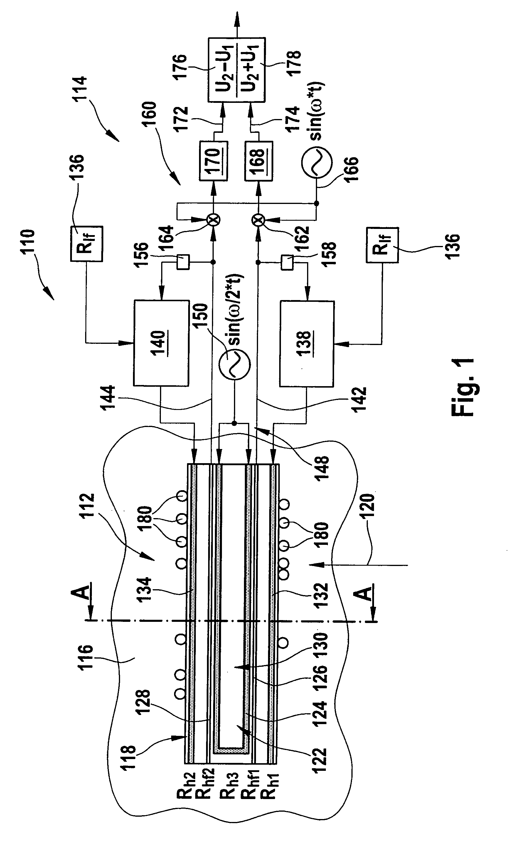
[0032]FIG. 1 schematically shows an exemplary embodiment of a hot-film air mass meter 110 according to the present invention. Hot-film air mass meter 110 has a sensor chip 112 (shown only in rudimentary form) and a control and evaluation circuit 114 (likewise shown only in rudimentary form). Sensor chip 112 may be used in the induction tract of an internal combustion engine, for instance, or in a bypass channel to the induction tract of an internal combustion engine. Such devices are known from DE 196 01 791 A1, for example. The sensor chip according to the development in FIG. 1 includes a chip mainland having a mainland surface 116 in the drawing plane (shown only in rudimentary form). In this exemplary embodiment it should be assumed that sensor chip 112 is a silicon sensor chip. In addition, sensor chip 112 includes a measuring region having a measuring surface 118 in the drawing plane. In this exemplary embodiment, measuring surface 118 is designed in the form of a rectangle who...


PUM


Abstract

A method for measuring an air mass flow flowing in a main flow direction, and a hot-film air mass meter by which the method is able to be realized. The method and the hot-film air mass meter are especially suitable for use in the induction tract of an internal combustion engine. The hot-film air mass meter includes a sensor chip having a chip surface across which an air mass flow is able to flow. The chip surface in turn has a measuring surface, the measuring surface including a central hot-film air mass meter circuit having at least one central heating element and at least two temperature sensors. The method is implemented so that the at least one central heating element is periodically heated using a frequency ω. With the aid of at least two temperature sensors, at least two measuring signals are detected. The measuring signals and / or at least one differential signal of the at least two measuring signals are modulated using the frequency ω.

Description

FIELD OF THE INVENTION[0001]The present invention relates to a hot-film air mass meter for measuring an air-mass flow that flows in a main flow direction, using frequency-modulated signal detection, and to a method for operating such a hot-film air mass meter. Hot-film air mass meters of this type are used in the induction tract of an internal combustion engine, in particular.BACKGROUND INFORMATION[0002]In many processes, for instance in the field of industrial process engineering, chemistry or machine construction, a gas mass, especially an air mass, has to be supplied in a specific manner. Among these are, in particular, combustion processes, which run under regulated conditions. An important example in this context is the combustion of fuel in internal combustion engines of motor vehicles, especially those having subsequent catalytic exhaust purification. Various types of sensors are used to measure the air-mass throughput.[0003]One sensor type from the related art is what is gen...

Claims


Application Information

Patent Timeline
IPC IPC(8): G01F1/692
CPCG01F1/6845G01F1/6986G01F1/692
Inventor OPITZ, BERNARDWAGNER, ULRICHFRANKE, AXELRAUDZIS, CARSTEN
Owner ROBERT BOSCH GMBH
Learn More