Bus station with integrated bus monitor function

a bus station and integrated technology, applied in the field of bus stations, can solve the problems of not being able unable to provide information in time, and using additional external, often very expensive equipment, etc., and achieve the effect of modifying electrical characteristics

Inactive Publication Date: 2006-06-22
VEGA GRIESHABER GMBH & CO
View PDF11 Cites 6 Cited by
  • Summary
  • Abstract
  • Description
  • Claims
  • Application Information

AI Technical Summary

Benefits of technology

[0024] A further advantage of the integration of the bus monitor function in a bus station is that it ensures that a negative effect due to modified electrical characteristics of the overall system are avoided since each bus station permanently stays within the system. Another advantage of the integration of the bus monitor function in a bus station is that, by permanently maintaining the bus station within the bus system, long-time diagnoses become possible enabling an investigation into a malfunction's potential cause.
[0029] As mentioned above, the data volume created by the bus monitor function is reduced by such a filtering function and therefore an on-line monitoring function is facilitated. The filtering function allows, for example, the recording of only those telegrams that are faulty when arriving at the bus station, in order to make them available to the user on-line during the running operation.

Problems solved by technology

A problem with this kind of networking of devices or bus stations with each other, however, is the possibility for monitoring or diagnosing the system in the case of a malfunction or for optimising the system.
An error detector determines whether the received packet contains an error, and produces an error detect signal and an error check result, if the receiver packet is determined as having an error.
The problem to be solved is to provide a network monitoring method and its equipment for finding and taking a countermeasure against disguise of a device.
If in such bus systems there are communication problems between one or more sensors or actuators and the control unit, the analysis of such problems involves considerable complexity, if a problem of this sort can be solved at all.
In these instances a conventional multipurpose meter is only rarely able to provide information on the cause of a faulty communication.
Often the only remaining possibility is to carry out monitoring or diagnosis of the bus system using additional external, often very expensive, equipment.
The advantage of an on-line filter is a reduction of the data volume to be stored; a disadvantage is, however, that possibly relevant telegrams are lost in the filtering process, resulting in incomplete recordings.
A disadvantage of such off-line filters is that they always cause very high data volumes.
By externally connecting these bus monitors to the bus system as passive devices, there is a danger that, as a side effect, they will influence the bus system as a consequence of changed electrical characteristics of the overall system, which can then lead to faulty diagnoses.
A further disadvantage of such external passive bus monitors is that they cannot achieve long-term diagnoses since they cannot continuously remain within the bus system.
Extensive trouble shooting is therefore often not possible since the bus monitors are not integrated in the bus system at the point in time when a malfunction occurs.
Moreover, such external bus systems are not suitable for error diagnosis because they only detect the local data traffic at the place where the bus monitor is connected.
Global monitoring, however, is not possible.

Method used


Image

  • Bus station with integrated bus monitor function
  • Bus station with integrated bus monitor function
  • Bus station with integrated bus monitor function

Examples


Embodiment Construction

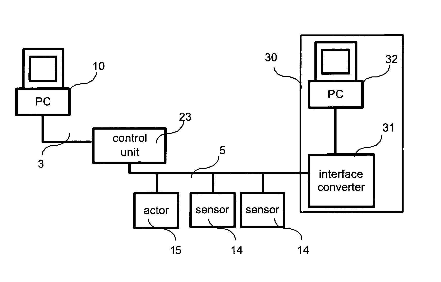
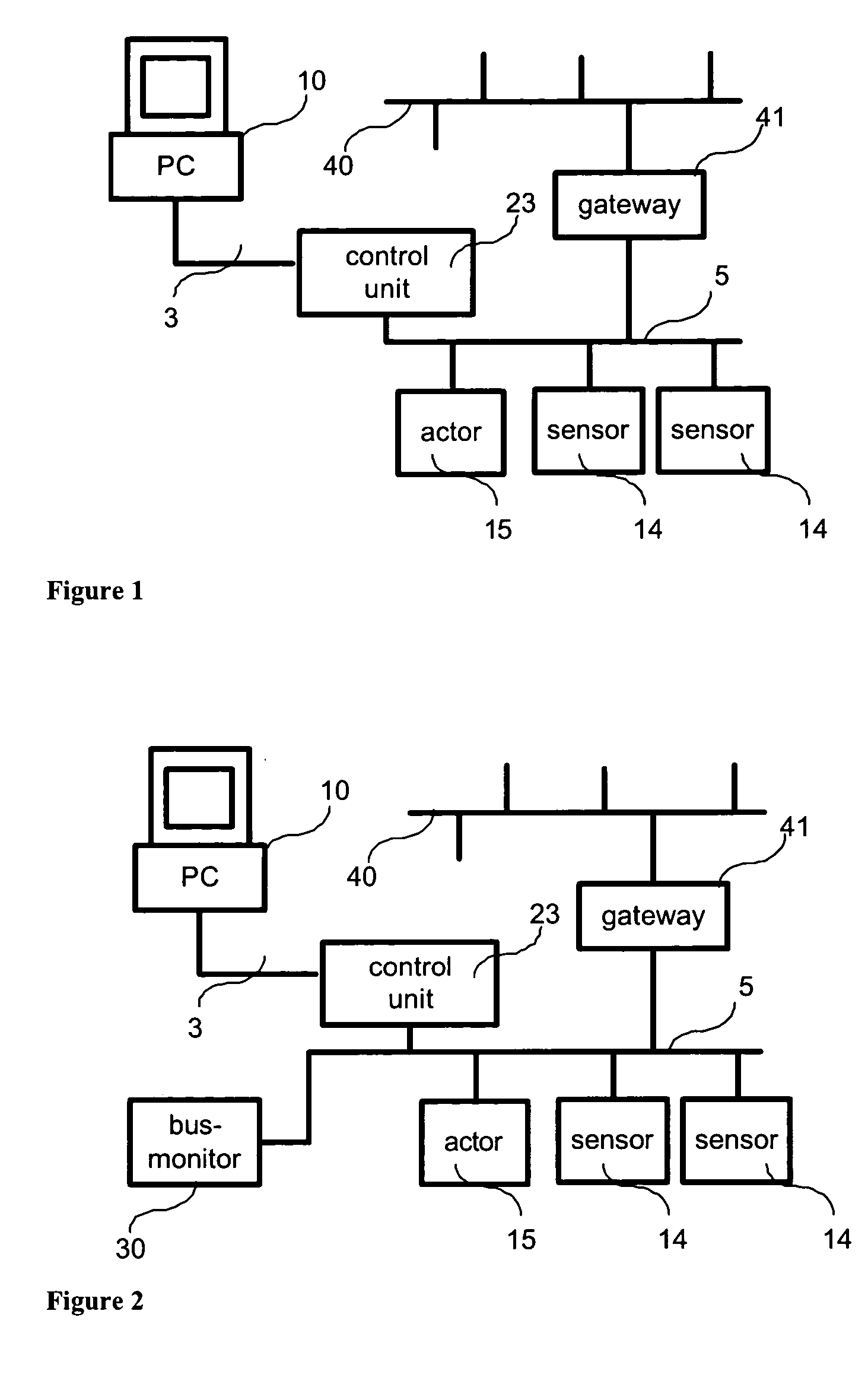
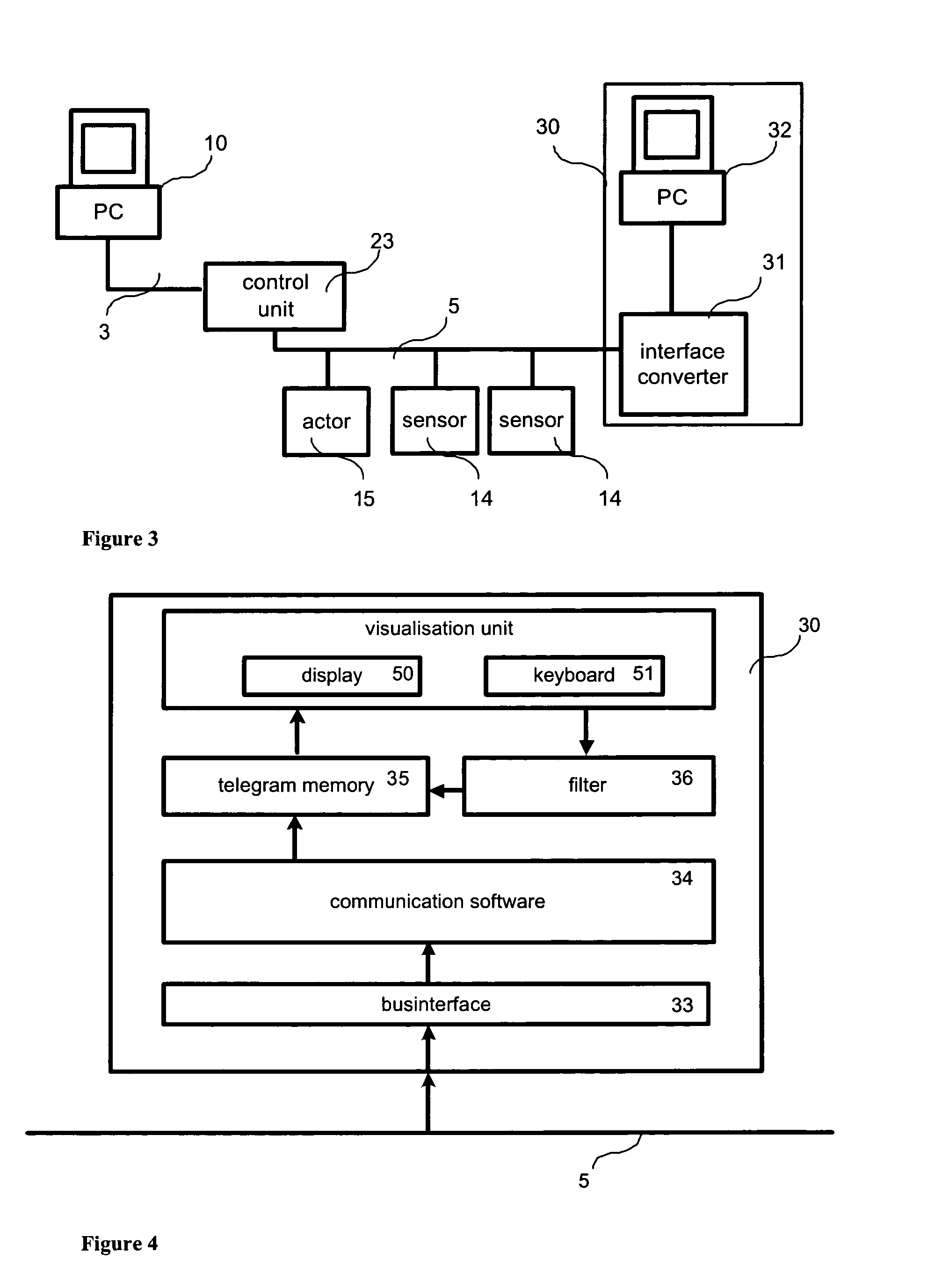
[0045]FIG. 1 shows the basic structure of a first digitally communicating bus system 5 with a control unit 23, sensors 14, and an actuator 15, each connected to the control unit 23 via the digitally communicating bus system 5. Control unit 23 may be any memory programmable controller (MPC) or specifically may be, for example, the evaluation center VEGALOG 571 of the company VEGA Grieshaber KG, Germany. The first bus system 5 may be any bus system, such as Fieldbus Foundation or Hart, however, Profibus PA or VBUS of the company VEGA Grieshaber KG, Germany, have turned out to be particularly suitable. In the present embodiment, control unit 23 has a configuration interface 3, in the present case coupled to a configuration computer 10. Configuration computer 10 is a common personal computer (PC) or may be a specific configuration device.

[0046] The first bus system 5 can be optionally complemented by a second bus system 40 via a gateway 41. The second bus system 40 represents an overla...


PUM


Abstract

Described is a bus station (e.g., a sensor, an actuator, a gateway) which performs a primary device function and a secondary function (e.g., a bus monitor function). To perform the secondary function, the bus station is equipped with a bus monitor arrangement which allows the bus station to access, to detect and to further process telegram traffic carried on the bus system. Also described is a network equipped with a plurality of such bus stations and a method for carrying out such monitoring with the aid of the bus stations.

Description

PRIORITY CLAIM [0001] This application is a Continuation application of U.S. patent application Ser. No. 10 / 623,199 filed on Jul. 18, 2003 which claims the benefit of U.S. Provisional Patent Application Ser. No. 60 / 397,558 filed on Jul. 18, 2002; the specifications of both applications are expressly incorporated herein, in their entirety, by reference.TECHNICAL FIELD [0002] The present invention relates to a bus station for integration into a bus system or for connection to a bus system. Furthermore, the present invention relates to a network with at least one such bus station and the use of such bus station for monitoring a bus system. [0003] A bus station provides other bus subscribers or bus stations via the bus system with process data or signals in the form of telegrams. Corresponding data and signals are preferably received by such bus station via the bus system. In particular, the present invention relates to a bus station in the field of filling level or pressure measurement...

Claims


Application Information

Patent Timeline
Patent Type & Authority Applications(United States)
IPC IPC(8): G06F13/14G01M99/00H04L12/24H04L12/26H04L12/40
CPCH04L12/2602H04L12/4625H04L41/0253H04L41/0604H04L43/00H04L43/028H04L43/062H04L43/0811H04L43/0817H04L43/106
Inventor GROS, THOMASFAIST, FRIDOLIN
Owner VEGA GRIESHABER GMBH & CO
Why Eureka
Try Eureka