
Apparatus and method for creating a flat surface on a workpiece

a technology of flat surface and workpiece, applied in the field of woodworking, can solve the problems of affecting the appearance of workpieces, and requiring a significant amount of skill/time to correct them, and achieving the effect of avoiding defects and avoiding defects

Inactive Publication Date: 2006-06-29
CHANG TYPE INDAL
View PDF10 Cites 8 Cited by
  • Summary
  • Abstract
  • Description
  • Claims
  • Application Information

AI Technical Summary

Benefits of technology

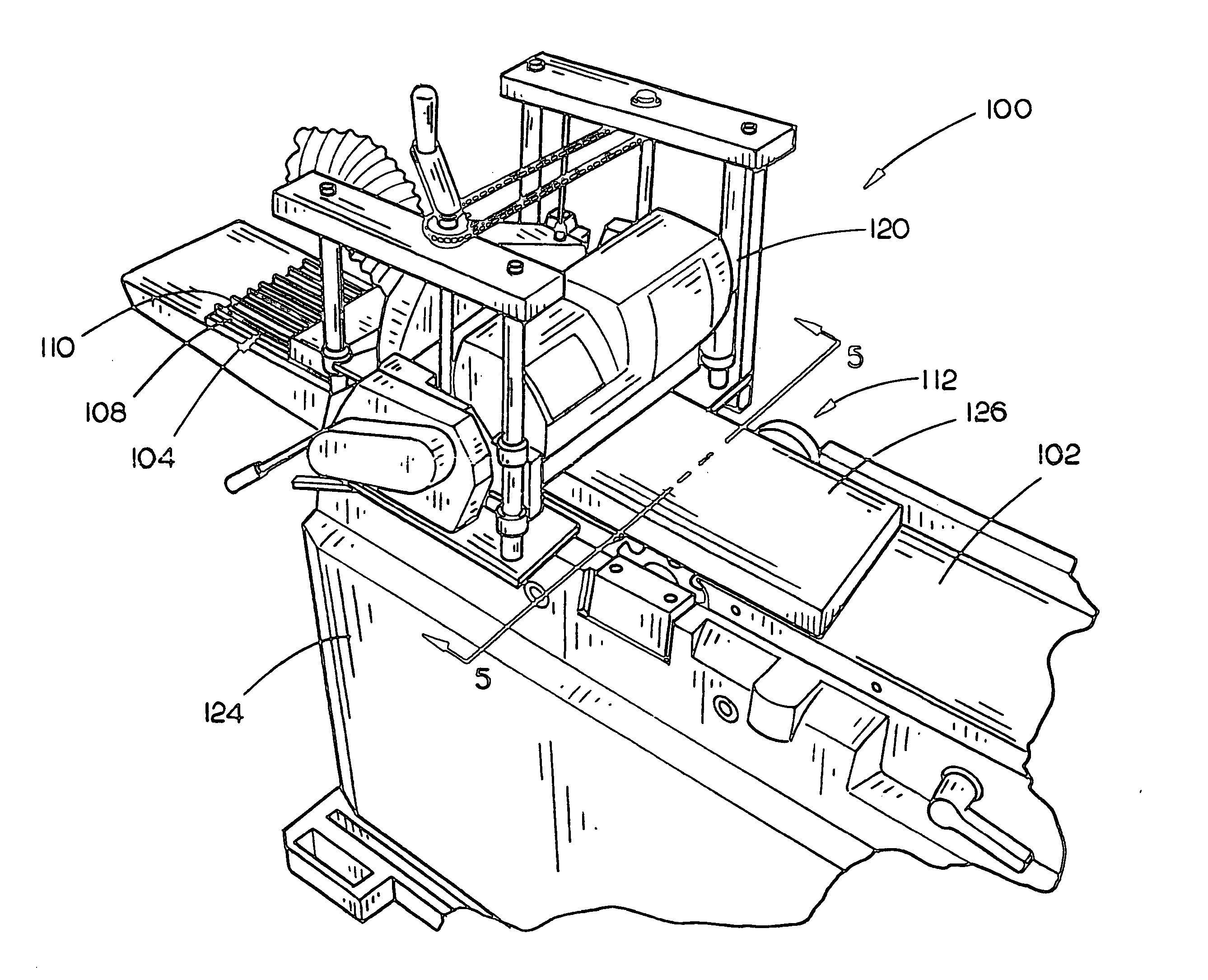
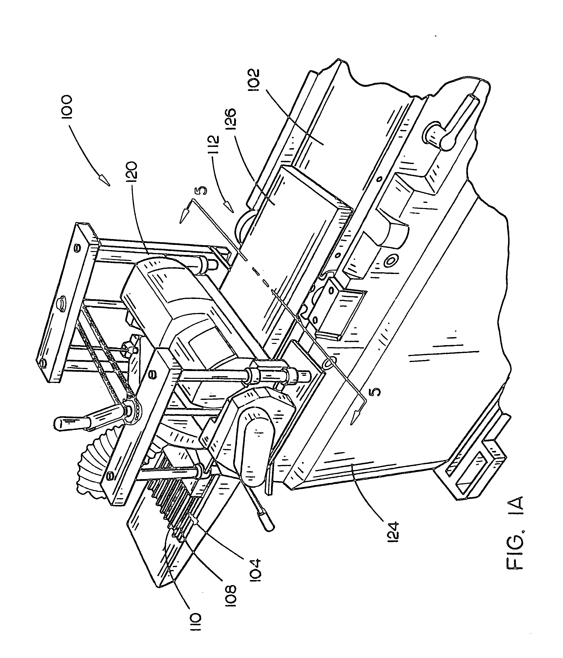
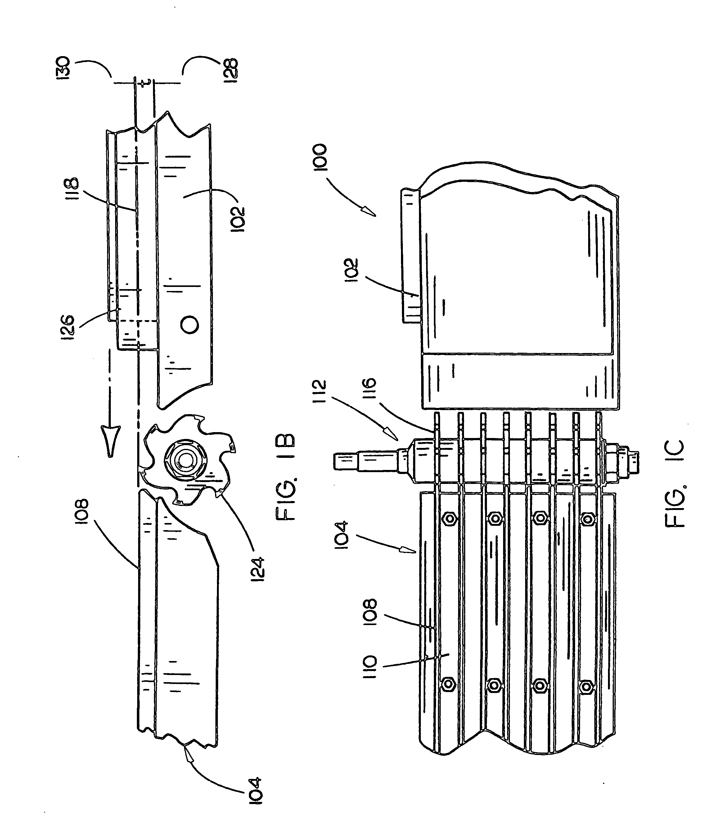
[0008] Accordingly, the present invention is directed to an apparatus for forming a flat surface on a workpiece via an intermediate datum plane. In an aspect of the invention, the apparatus includes a cutterhead having a plurality of cutting members configured for forming a plurality of grooves in a workpiece. In the present aspect, the cutterhead is disposed generally at the interface of substantially parallel offset first and a second supports in order to form a plurality of grooves defining a datum or reference plane. The intermediate grooves / datum plane may be implemented to orientate the workpiece for forming a flat surface referenced to the datum plane. A plurality of ridges or the like structures defining grooves are included in the second support or as an attachment to the second support in order to support the workpiece from the material forming the interior surface of the grooves so the workpiece may be orientated with respect to the datum plane.

Problems solved by technology

Due to varying transport and storage conditions, lumber may deform or include defects due to improper storage, variations in humidity, temperature variations, and the like.
Correction of these defects often requires a significant amount of skill / time in order to insure a proper finish such as a proper face joint between adjacent boards in cabinet panel.
In some instances, mock defects may be created if a user stresses the workpiece during shaping operations.
Excessive down-pressure on a bowed piece of lumber, during jointing operations, may cause the board to deform back into a bowed, or cupped shape, once pressure is relieved; thereby failing to properly finish the board.
Further problems may include a workpiece being twisted or rocked between an infeed table and outfeed table during jointing operation.
In the previous example, the resulting workpiece may include a non-uniform edge requiring further refining prior to utilization in the project.
In practice, this goal may be difficult for a novice to achieve or may be time consuming.
In some instances, a planer may fail to correct the defect and merely result in a nominal correction or a thinner board which still contains the defect.
Even when removing relatively small amounts of wood (i.e., a fraction of an inch), an operator may have to feed the material at a slow rate due to the feed pressure and power required to complete the operation.
In the foregoing instance, a novice user may tend to force the workpiece thereby resulting in a rough edge.
Furthermore, as most jointers are retailed with a 6″ or 8″ (six inch or eight inch) cutter, the effective capacity of these devices is limited.

Method used


Image

  • Apparatus and method for creating a flat surface on a workpiece
  • Apparatus and method for creating a flat surface on a workpiece
  • Apparatus and method for creating a flat surface on a workpiece

Examples


Embodiment Construction

[0026] Reference will now be made in detail to the presently preferred embodiments of the invention, examples of which are illustrated in the accompanying drawings. It is to be appreciated that corresponding reference numbers refer to generally corresponding structures throughout.

[0027] Referring to FIGS. 1A-1C, a surfacing apparatus 100 in accordance with an embodiment of the present invention is disclosed. The apparatus 100 permits the formation of a plurality of grooves which correspond to an intermediate datum plane in a workpiece 126 such that a flat surface may be obtained in an efficient manner. For example, lumber such as a board or plank may have a variety of defects, or abnormalities, which make it unsuitable for its intended purpose (in a retailed condition). As noted previously, hardwood lumber often is retailed with these defects and it is the responsibility of the end user to correct the workpiece's deficiencies prior to use. In order for a user to implement the workp...


PUM


Abstract

An apparatus and method for forming a flat surface on a workpiece. The apparatus includes a cutterhead, having a plurality of cutting member, configured for forming a plurality of grooves in a workpiece. The cutterhead may be disposed generally at the interface of substantially parallel offset first and a second supports in order to form a plurality of grooves defining a datum or reference plane which may be implemented to orientate the workpiece for forming a flat surface. A plurality of ridges or the like structures defining grooves are included in the second support or as an attachment to the second support in order to support the workpiece from the material forming the interior surface of the grooves so that the workpiece may be orientated with respect to the datum plane. In an additional aspect, a second cutterhead may be included for removing or forming a flat surface which is parallel to the datum plane.

Description

CROSS REFERENCE [0001] The present application claims priority as a Continuation-In-Part under 35 U.S.C. §120 to U.S. patent application Ser. No. 11 / 021,486, entitled: Apparatus and Method for Creating a Flat Surface on a Workpiece, filed on Dec. 23, 2004, which is hereby incorporated by reference in its entirety.FIELD OF THE INVENTION [0002] The present invention relates to the field of woodworking and particularly to an apparatus and method for generating a flat surface on a workpiece. BACKGROUND OF THE INVENTION [0003] Woodworkers often have to “true-up”, or form lumber into flat surfaces, as part of a woodworking project. For example, most hardwood lumber or boards for cabinetry type purposes are typically sold in a relatively rough form. Due to varying transport and storage conditions, lumber may deform or include defects due to improper storage, variations in humidity, temperature variations, and the like. A hardwood board often is retailed with various defects or abnormalitie...

Claims


Application Information

Patent Timeline
IPC IPC(8): B27C1/00
CPCB27C1/02B27C1/12B27F5/026
Inventor GARCIA, JAIME E.CARROLL, CRAIG A.
Owner CHANG TYPE INDAL
Learn More