Ink Jet Printer

a technology of inkjet printer and ink jet, which is applied in the direction of printing, other printing apparatus, etc., can solve the problems of unnecessarily consuming cleaning liquid in large quantities, increasing the size of ink jet printer, etc., and achieves the effect of recovering or maintaining the ability of ink and maintaining good print quality

Inactive Publication Date: 2006-06-29
RISO KAGAKU CORP +1
View PDF74 Cites 13 Cited by
  • Summary
  • Abstract
  • Description
  • Claims
  • Application Information

AI Technical Summary

Benefits of technology

[0010] When the flushing process is frequently performed, it will be possible to recover or maintain the ability of the ink to be jetted from the nozzles, by simply executing the flushing process for short periods of time. Accordingly, the present inventors created an ink jet printer that executes the flushing process each time printing is performed on one printing sheet. In this situation, because the flushing process will be completed in a short period of time, the area on the endless belt on which the ink jetted during the flushing process will adhere will be narrow. When two printing sheets are to be carried on the endless belt in a positional relationship in which a small gap is maintained therebetween during consecutive printing, the flushing process can be completed while ink is jetted toward that gap. According to this method, a printing process on one printing sheet is sequentially executed with the flushing process, and good print quality can be maintained thereby.
[0011] In this method, the ink that was jetted for the flushing process will adhere intermittently to the endless belt. In other words, there is a gap between the position on the endless belt to which the ink jetted for the previous flushing process is adhered, and the position on the endless belt to which the ink jetted for the next flushing process will be adhered, and thus the endless belt will not be soiled in that gap.
[0015] The present invention serves to solve the aforementioned problems, and provides technology that accurately dispenses cleaning liquid in locations on an endless belt on which ink is adhered.
[0018] In the example shown in FIG. 10, the state in which the cleaning liquid dispenser 208 dispenses cleaning liquid on the endless belt (the state shown in FIG. 10(14)), and the state in which the cleaning liquid dispenser 208 does not dispense cleaning liquid on the endless belt (the state shown in FIG. 10(13)), will be switched by a device that moves mechanically (a rotator 210 in this example). When mechanical movement is used to switch the state of the cleaning liquid dispenser 208, it becomes possible to match the position in which the ink 206 is adhered to the position in which the cleaning liquid is dispensed, even if the carry speed of the endless belt is fast.
[0021] According to the ink jet printer of the present invention, the rotation of the endless belt will be mechanically synchronized with the movement of the mechanical shifter to switch the state of the dispenser. In this way, it will be possible to intensively dispense the cleaning liquid in a position in which ink has adhered, even if the carry speed of the endless belt is high. Wasteful consumption of the cleaning liquid can be prevented. In addition, a large cleaning liquid tank will be unnecessary, and the size of the ink jet printer can be reduced.
[0023] Furthermore, because the dispensing operation of the cleaning liquid is mechanically synchronized with the rotation of the endless belt, the position in which the ink is adhered on the endless belt can be matched with the dispensing position of the cleaning liquid, and the cleaning liquid can be reliably dispensed in the necessary positions.

Problems solved by technology

The cleaning liquid is unnecessarily consumed in large quantities.
In addition, a large cleaning liquid tank will be necessary, which will increase the size of the ink jet printer.

Method used


Image

  • Ink Jet Printer
  • Ink Jet Printer
  • Ink Jet Printer

Examples


third embodiment

[0194] As described above in the third embodiment, due to the rotational movement of the eccentric cam 140, cleaning liquid can be intermittently dispensed, and dispensed so as to match a flushing region, even by contacting and separating the sponge member 41 arranged on the plate member 142 with respect to the endless belt 8.

[0195] Next, a fourth embodiment will be explained with reference to FIG. 14. In the first embodiment, the cleaning liquid dispenser 55 is constructed so as to dispense cleaning liquid on the endless belt by contacting the sponge member 41 on the endless belt 8. Instead of this, the cleaning liquid dispenser of the fourth embodiment is constructed so as to jet cleaning liquid onto the endless belt 8, and dispense cleaning liquid on the endless belt 8 without contact, in accordance with the rotational movement of the rotator 40. Note that the components that are identical to the aforementioned first embodiment have the same reference numerals, and a description ...

fourth embodiment

[0196]FIG. 14 is a partially enlarged view of a cleaning liquid dispenser 255 in the The rotator 40 is arranged below the belt roller 7a, and the cleaning liquid dispenser 255 comprises a sprayer 255 that jets cleaning liquid onto the endless belt 8 in accordance with the rotational movement of the rotator 40.

[0197] The sprayer 260 is arranged between the rotator 40 and the endless belt 8, and comprises a hollow and substantially cylindrical shaped cylinder 255 that stores cleaning liquid. A nozzle (conduction port) that is the dispensing port for the cleaning liquid projects on the tip of the cylinder 255 toward the endless belt 8. A piston 254 that slides on the inner wall of the cylinder 255 is arranged inside the cylinder 255. The piston 254 is formed in a substantially cylindrical shape that extends along the lengthwise direction of the cylinder 255, and is formed to be longer than the cylinder 255. The tip side of the piston 254 (the cylinder 255 side) is covered by an elasti...

fifth embodiment

[0205] As described in the fifth embodiment above, because the sub-tank 50 is arranged above the main tank 51, cleaning liquid will be dispensed from the main tank 51 by means of the pump 59. Moreover, because cleaning liquid is not dispensed to the sub-tank so long as it is not fed by a pump, carelessly dispensing the cleaning fluid from the main tank to the sub-tank due to the head difference, and overflowing the cleaning liquid from the sub-tank 50, can be avoided even if the flow path of the cleaning fluid is left open.

[0206] The present invention was described above based upon the embodiments, however the present invention is not in any way limited to the aforementioned embodiments. The possibility of various improvements and modifications can be easily imagined within a range that does not depart from the essence of the present invention.

[0207] For example, in the aforementioned embodiments, the printer 1 was constructed so as to perform a flushing each time a printing sheet ...


PUM


Abstract

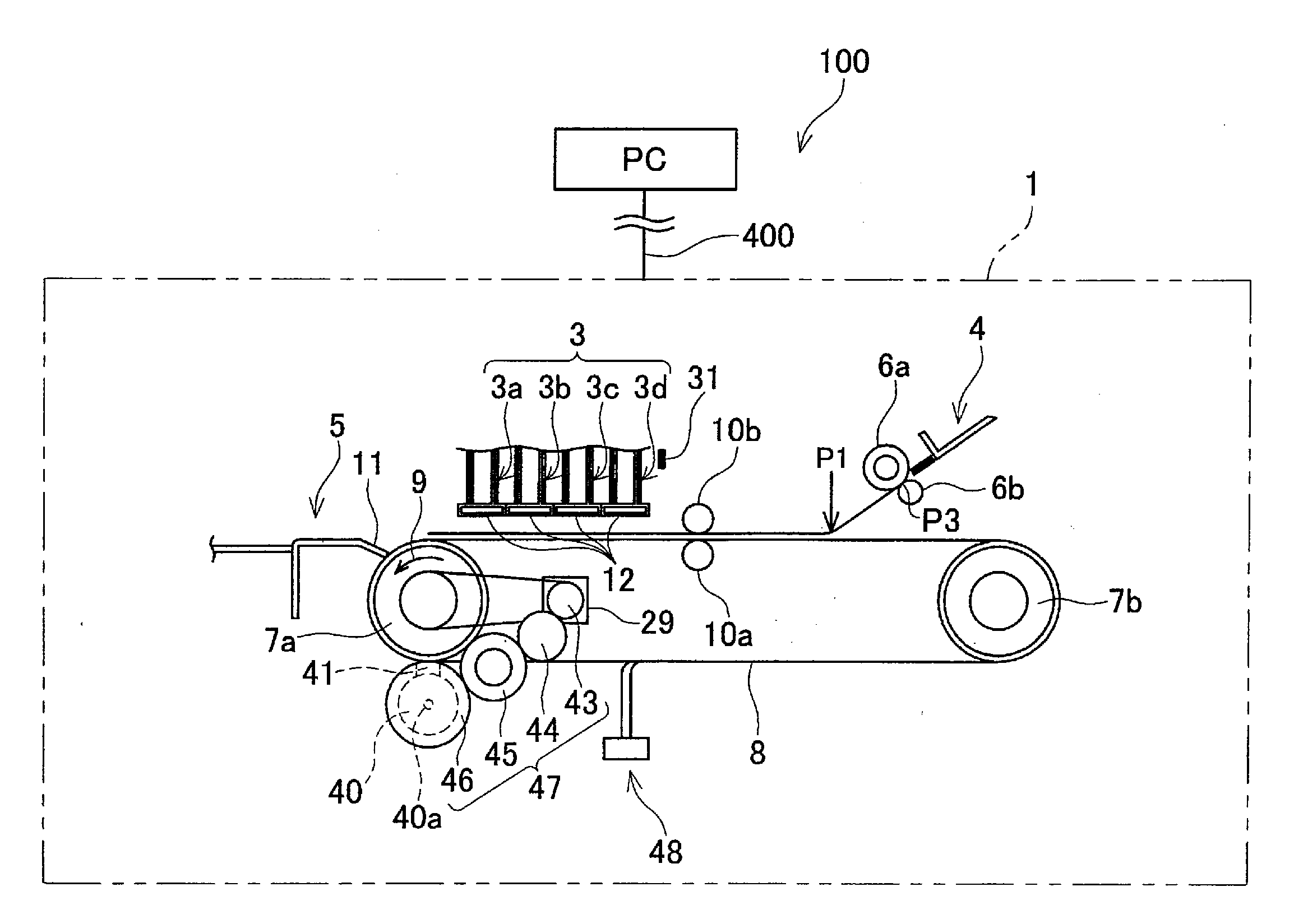
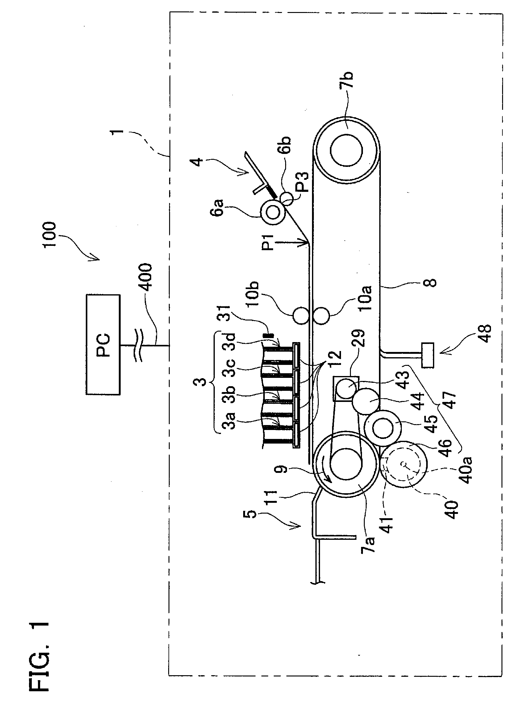
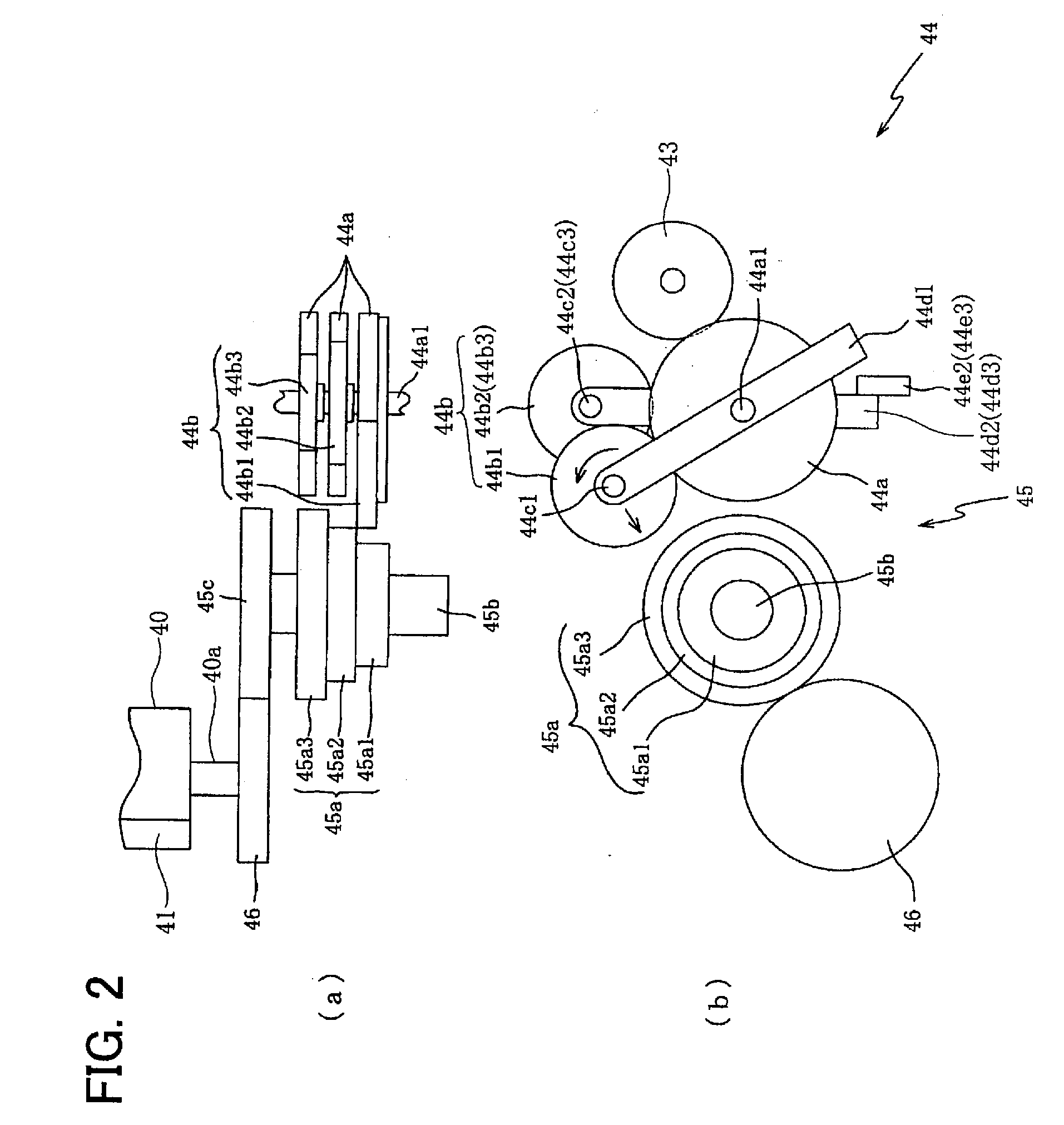
An ink jet printer is provided, which intermittently dispenses cleaning liquid onto ink that is adhered to an endless belt that carries printing sheets. A cleaning liquid dispenser is driven by a rotator that rotates in association with the rotation of the endless belt. The rotation position of the rotator is set as a reference, in order to control the feed timing. In this way, a gap can be maintained between two printing sheets that are carried by the endless belt, ink can be jetted toward the gap, and cleaning liquid can be dispensed on the gap. A print process and a flushing process can be sequentially repeated.

Description

CROSS-REFERENCE TO RELATED APPLICATION [0001] This application claims priority to Japanese Patent Application No. 2004-372645 filed on Dec. 24, 2004, the contents of which are hereby incorporated by reference into the present application. BACKGROUND OF THE INVENTION [0002] 1. Field of the Invention [0003] The present invention relates to an inkjet printer. More particularly, the present invention relates to an ink jet printer that executes a process that jets ink from nozzles in order to print and a process that jets ink from the nozzles in order to clean the nozzles, and has a function which cleans the ink that was jetted in order to clean the nozzles. [0004] 2. Description of the Related Art [0005] An ink jet printer comprises a plurality of nozzles, and prints on a printing sheet by jetting ink from the nozzles. The diameters of the nozzles are extremely small, and there are times in which the nozzles will become clogged. Or, there may be times in which air bubbles become mixed w...

Claims


Application Information

Patent Timeline
Patent Type & Authority Applications(United States)
IPC IPC(8): B41J2/165
CPCB41J13/0018B41J13/08B41J29/17
Inventor NAKASHIMA, ATSUHISAKUZUYA, SUSUMU
Owner RISO KAGAKU CORP
Why Eureka
Try Eureka