System and method for object measurement

a measurement system and measurement method technology, applied in the field of industrial metrology, can solve the problems of inability to employ current techniques based on point correspondence, high maintenance, and high cost of these measurement systems

Active Publication Date: 2006-06-29
GENERAL ELECTRIC CO
View PDF6 Cites 130 Cited by
  • Summary
  • Abstract
  • Description
  • Claims
  • Application Information

AI Technical Summary

Problems solved by technology

Unfortunately, many of these measurement systems are costly, slow to produce, bulky, application specific, and require high maintenance.
Also, in many applications the tubes considered are smooth surfaces without texture or fiducial markings, and therefore current techniques that rely on point correspondences cannot be employed, as the accuracy level is lower than acceptable.

Method used


Image

  • System and method for object measurement
  • System and method for object measurement
  • System and method for object measurement

Examples


Embodiment Construction

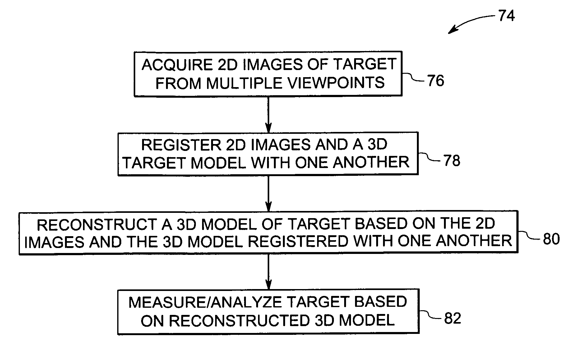
[0013] Embodiments of the present technique are generally directed toward a method and system for model-based measurement using images of multiple views of an object / target. These measurement techniques may be useful in a variety of contexts where a complex part, such as a curved section of a tube, needs to be measured and compared against design parameters. Although the following discussion is limited to a few examples, a variety of applications are within the scope of the present technique.

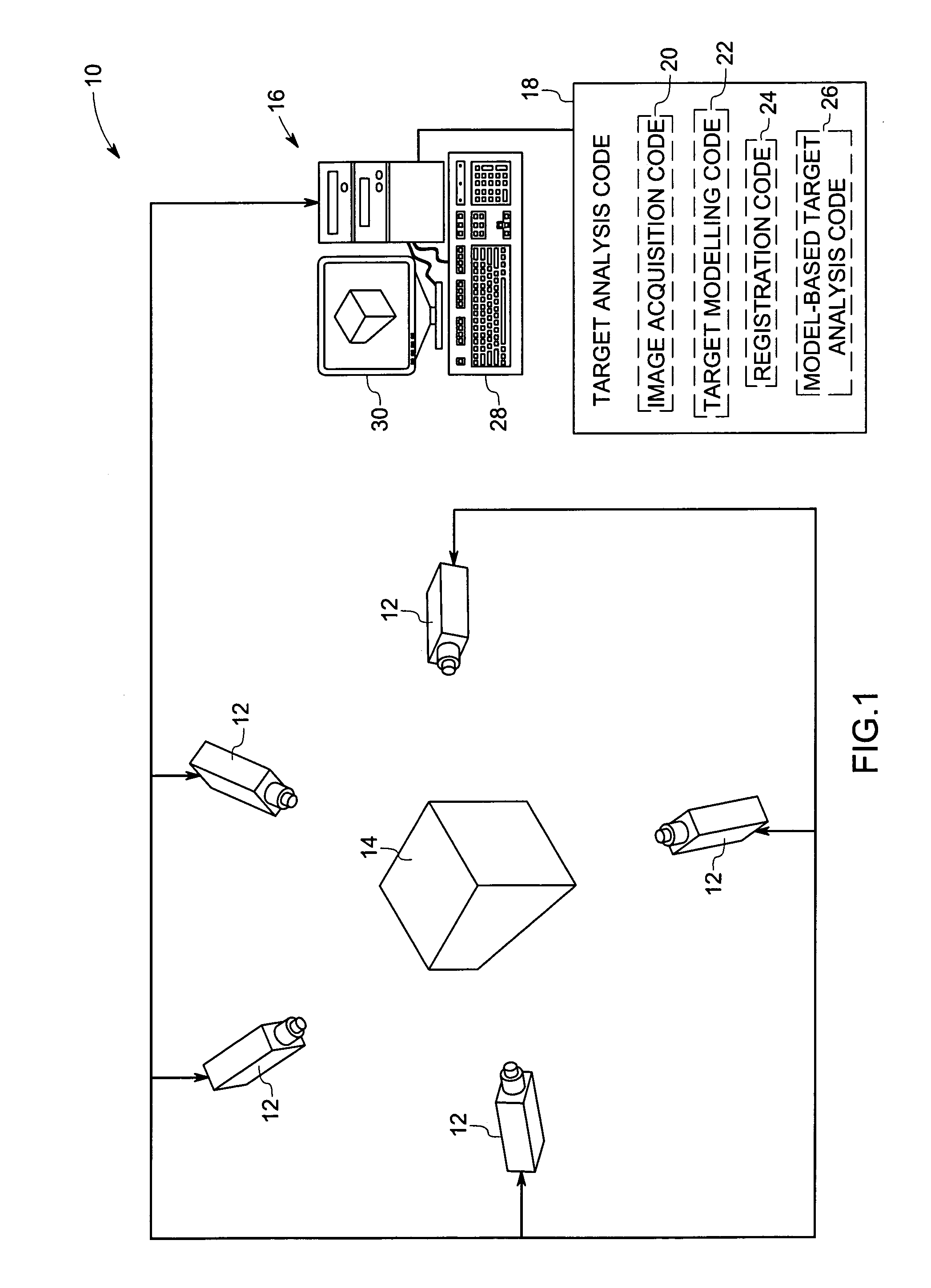
[0014] Referring now to FIG. 1, this figure illustrates an exemplary measurement system 10 in accordance with the present technique. In the illustrated embodiment, the measurement system 10 may include one or more imaging devices 12 placed at various viewpoints for acquiring multiple images of an object / target 14 under inspection. In certain embodiments, the imaging devices 12 may be analog and / or digital cameras, such as still or video cameras. Alternatively, a single imaging device 12 may be ...


PUM


Abstract

A technique is provided for measuring an object based on multiple views. The technique includes registering each of the plurality of images and a first model of the object with one another and reconstructing a second model of the object based on the plurality of images and the first model registered with one another.

Description

BACKGROUND [0001] The invention relates generally to the field of industrial metrology and, in particular, to model-based measurement techniques using multiple views. [0002] Measurement of objects is of vital importance in manufacturing and repair industries. Various types of measurement systems, such as computed tomography (CT), coordinate measuring machines (CMM), laser-based profilometry, and infrared, are used for industrial inspection. For example, these measurement systems may be used for measuring dimensions or for identifying defects in manufactured parts, such as tubes. Unfortunately, many of these measurement systems are costly, slow to produce, bulky, application specific, and require high maintenance. For example, different gauges are often required for different tubes. Also, in many applications the tubes considered are smooth surfaces without texture or fiducial markings, and therefore current techniques that rely on point correspondences cannot be employed, as the acc...

Claims


Application Information

Patent Timeline
Patent Type & Authority Applications(United States)
IPC IPC(8): G06K9/00G06K9/36
CPCG01N21/9515G01N21/952G01B11/022G06T7/001G06T7/0028G06K9/00208G06T7/33G06V20/647
Inventor BROOKSBY, GLEN WILLIAMSANTOS MENDONCA, PAULO RICARDO DOSBORGES, DENISA NARMOUR
Owner GENERAL ELECTRIC CO
Why Eureka
Try Eureka