Prevention of unnecessary hand-over caused by fading

Inactive Publication Date: 2006-06-29
LENOVO INNOVATIONS LTD HONG KONG
View PDF4 Cites 6 Cited by
  • Summary
  • Abstract
  • Description
  • Claims
  • Application Information

AI Technical Summary

Benefits of technology

[0018] It is an object of the present invention is to provide a method of preventing unnecessary hand-over caused by fading in an effective and simple manner.
[0019] To this end, the method according to the present invention is intended to prevent unnecessary hand-over caused by fading in the following procedure.
[0024] Thus, according to the present invention, the use of the algorithm based on the properties of fading that the received power is fluctuated within a predetermined strength range, prevents unnecessary hand-over caused by fading in an effective and simple manner, thereby preventing the failure to perform necessary hand-over and therefore disconnection of communication

Problems solved by technology

In radio communications, fading may occur due to buildings and geographical features, causing fluctuation of the received power from each radio communication base station.
However, because radio communication terminal 41 performs hand-over to switch between the radio communication base stations in cells C and D, it cannot perform hand-over to the radio communication base station in cell E. This causes a problem that a call is undesirably disconnected due to the deterioration of the qualities of received signals from the radio communication base stations in cells A and B.
In this way, in situations where hand-over to switch between two cells C, D is frequently performed, the hand-over that is necessary to maintain communications with radio communication terminal 41 cannot be performed due to unnecessary hand-over that has been frequently performed.

Method used


Image

  • Prevention of unnecessary hand-over caused by fading
  • Prevention of unnecessary hand-over caused by fading
  • Prevention of unnecessary hand-over caused by fading

Examples


Embodiment Construction

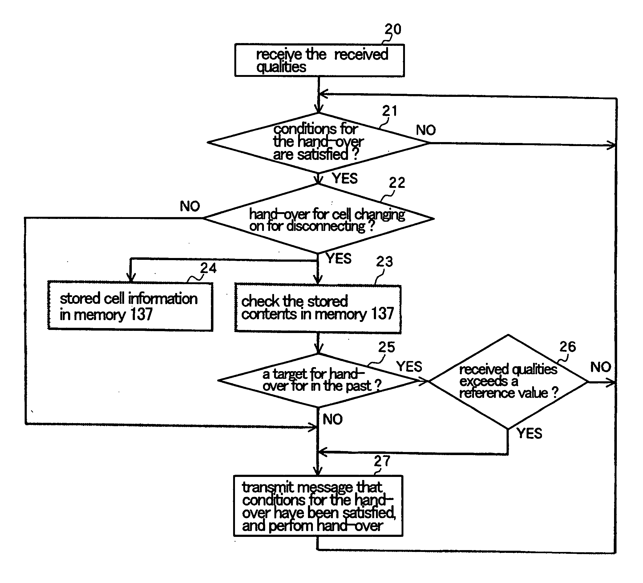
[0033] Referring now to FIG. 6, a radio communication terminal according to an embodiment of the present invention comprises antenna 10, antenna sharing unit 11, radio receiver 12, baseband receiver 13, radio transmitter 14, and base band transmitter 15. Baseband receiver 13 includes a plurality of finger receivers 131, 132 and 133, peripheral cell measuring finger receiver 134, digital signal processor 135, hand-over controller 136, and hand-over control memory 137.

[0034] Antenna 10 receives and transmits signals for communication with radio communication base stations (not shown).

[0035] Antenna sharing unit 11 supplies the signal received by antenna 10 to radio receiver 12 and outputs to antenna 10 a transmission signal of the radio communication terminal that is output from radio transmitter 14.

[0036] Radio receiver 12 performs radio processing such as frequency conversion and the like on the received signal to supply the resultant signal as a received signal within a baseband...


PUM


Abstract

A hand-over control method is disclosed to control the change of connections between a radio communication terminal and a plurality of radio communication base stations for radio communication. The received power of a signal from a radio communication base station in a cell that that is subject to the influence of fading is likely to vibrate within a predetermined strength range. Even if a cell satisfies hand-over conditions, there is a greater likelihood that the cell is still subject to the influence of fading, if the received power is not exceeding this predetermined range The current received quality of a signal from a radio communication terminal in the cell is compared with last received quality of the signal from the radio communication base station when the radio communication terminal finished radio communication with radio communication base station. If the former quality is not higher than the latter quality by a predetermined level or more, the radio communication base station is determined to still be subject to the influence of fading, and hand-over is not performed. If, on the other hand, the former quality is higher than the latter quality by the predetermined level or more, the radio communication base station is determined not to be subject to the influence of fading, and hand-over is not performed.

Description

BACKGROUND OF THE INVENTION [0001] 1. Field of the Invention [0002] The present invention relates to a method of controlling hand-over (change of radio communication base stations to be connected) performed by a radio communication terminal such as a portable telephone or the like. [0003] 2. Description of Related Art [0004]FIG. 1 is a schematic diagram illustrating a radio communication system to explain hand-over performed by radio communication terminal. In FIG. 1, cell A indicates an area in which radio communication terminal 31 can perform a radio communication with radio communication base station 32, and cell B indicates an area in which radio communication terminal 31 can perform a radio communication with radio communication base station 33. Hand-over performed by radio communication terminal 31 refers to an operation in which radio communication terminal 31 which is communicating with radio communication base station 32 change radio communication with radio communication b...

Claims


Application Information

Patent Timeline
IPC IPC(8): H04Q7/20H04W36/08H04W36/30
CPCH04W36/245H04W36/30H04W36/008375H04W36/304
Inventor TAKAKI, TETSUYA
Owner LENOVO INNOVATIONS LTD HONG KONG
Why Eureka
Try Eureka