Eject-lever apparatus for optical transceiver

Inactive Publication Date: 2006-07-06
IND TECH RES INST
View PDF4 Cites 5 Cited by
  • Summary
  • Abstract
  • Description
  • Claims
  • Application Information

AI Technical Summary

Benefits of technology

[0012] It is the primary object of the invention to provide an eject-lever apparatus for an optical transceiver, capable of enabling the disengagement of the optical transceiver from a slot of a housing by using an reacting force provided by a linkage mechanism of the eject-lever apparatus and thus enduring the wear of time.
[0014] It is yet another object of the invention to provide an eject-lever apparatus for an optical transceiver, capable of using a linkage mechanism thereof to disengage the optical transceiver from a slot of a housing while minimizing the use of spring tabs and maximizing shielding effect.
[0015] To achieve the above objects, the present invention provides an eject-lever apparatus, arranged in an optical transceiver having a substrate, where the optical transceiver is received in a housing having a slot arranged therein while the substrate is plugged in the slot, the eject-lever apparatus comprising: at least a lever having a cam arranged therein, being disposed at the receiving end of the optic fiber of the optical transceiver; and at least a linkage mechanism, being deposed on a side of the optical transceiver; wherein the lever is actuated to rotate about an axis from a first location thereof to a second position thereof by exerting a force thereon while driving the cam to rotate accordingly for transmitting the force to an end of the linkage rod enabling the linkage rod to exert a force on the housing so as to generate a reacting force acting on the lever and thus cause the optical transceiver to move out to compress an elastic body and be ejected from the slot gradually; finally, the substrate is totally released from the slot for freeing the optical transceiver from the housing while the lever is in the second position, and thereafter, a resilience force generated by the compressed elastic body enables the returning of the lever from the second position to the first position while the lever is lightly moved to escape the contacting position with the linkage rod.

Problems solved by technology

A poor configuration or poorly designed releasing means not only may worsen the manufacturing cost, but also can cause a certain maintenance difficulties, and more particularly, the poorly designed releasing means might cause the damage of the optical transceiver or the optical fiber connected thereto during an releasing process and thus affect the performance and life span of the optical transceivers.
(2) The spring tab might block the way for obstructing the installation of the optical transceiver while the triangular latch is damaged or not functioning properly.
(3) The cracks of the spring tabs due to a finishing process might cause electromagnetic interference.

Method used


Image

  • Eject-lever apparatus for optical transceiver
  • Eject-lever apparatus for optical transceiver
  • Eject-lever apparatus for optical transceiver

Examples


Embodiment Construction

[0025] For your esteemed members of reviewing committee to further understand and recognize the fulfilled functions and structural characteristics of the invention, several preferable embodiments cooperating with detailed description are presented as the follows.

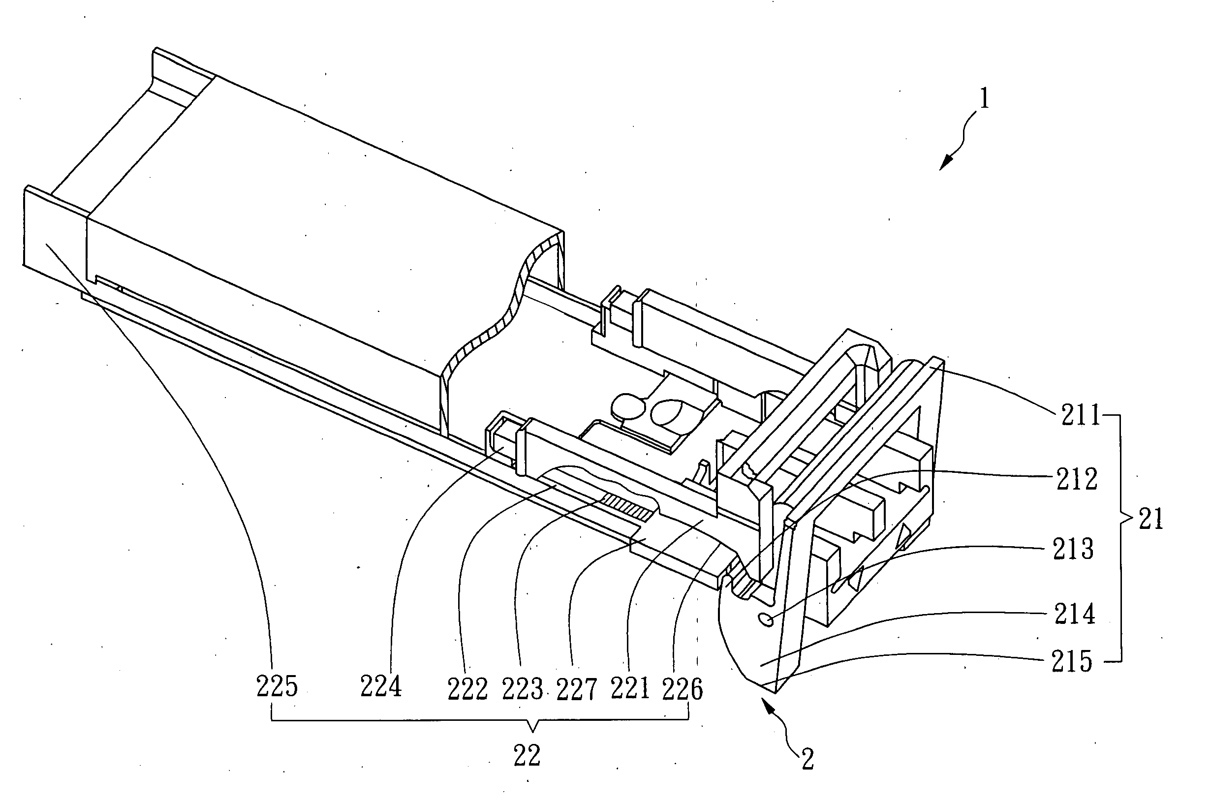
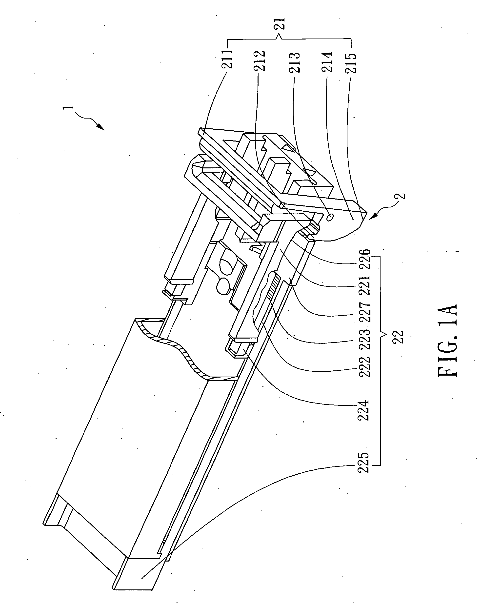
[0026] Please refer to FIG. 1A, which is a schematic view of an eject-lever apparatus for an optical transceiver according to a preferred embodiment of the invention. In FIG. 1A, an eject-lever apparatus 2 is attached to an optical transceiver 1 and is composed of a lever unit 21 and a pair of eject units 22, disposed at the two sides of the optical transceiver 1 in respective.

[0027] The lever unit 21 further comprises a lever 211, a pair of cams 214, a pair of axes 213, and a pair of hook-like parts 212. Wherein, the lever 211 is disposed over the optical transceiver 1 while the cams 214, the axes 213 and the hook-like part 212 are disposed at the two frontal sides of the optical transceiver 1 in respective with each cam ...


PUM


Abstract

The eject-lever apparatus of the present invention is arranged in an optical transceiver having a substrate, where the optical transceiver is being received in a housing having a slot arranged therein with the substrate being plugged into the slot, the apparatus comprising: at least a lever having a cam arranged therein, being disposed at the receiving end of the optic fiber of the optical transceiver; and at least a linkage rod, being deposed on a side of the optical transceiver, wherein the lever is actuated to rotate about an axis from a first location thereof to a second position thereof by exerting a force thereon while driving the cam to rotate accordingly for transmitting the force to an end of the linkage rod enabling the linkage rod to exert a force on the housing so as to generate a reacting force acting on the lever and thus cause the optical transceiver to move out to compress an elastic body and be ejected from the slot gradually; finally, the substrate is totally released from the slot for freeing the optical transceiver from the housing while the lever is in the second position, and thereafter, a resilience force generated by the compressed elastic body enables the returning of the lever from the second position to the first position while the lever is lightly moved.

Description

FIELD OF THE INVENTION [0001] The present invention relates to an eject-lever apparatus for an optical transceiver, and more particularly, to an eject-lever apparatus capable of ejecting an optical transceiver out a housing by using a mechanism of lever and linkage rod to force the substrate of the optical transceiver to disengage from a receptacle of the housing. BACKGROUND OF THE INVENTION [0002] By way of review, an optical transceiver is an integrated fiber optic component including an optical transmitter and an optical receiver, which is capable of providing bi-directional transmission of data between an electrical interface and an optical data link. The optical transceiver receives and converts electrically encoded data signals into optical signals which are then transmitted over the optical data link. Likewise, the optical transceiver receives and converts optically encoded data signals into electrical signals and transmits the electrical signals in the electrical interface. ...

Claims


Application Information

Patent Timeline
IPC IPC(8): H05K5/02
CPCG02B6/4246G02B6/4284
Inventor WU, ZONG-YUANLIN, WEN-SHANWEI, CHIA-PINGYU, JIUN-SHIANCHANG, JIN-SHENGCHEN, JUNG-TAI
Owner IND TECH RES INST
Why Eureka
Try Eureka