Multi-functional exercising device

a multi-functional, exercise technology, applied in gymnastics, resistance force resistors, frictional force resistors, etc., can solve the problems of complex structure of conventional exercise devices, high cost, and limited use of conventional indoor exercise devices, and achieve the effect of being versatile in us

Inactive Publication Date: 2006-07-06
CHEN PING
View PDF0 Cites 67 Cited by
  • Summary
  • Abstract
  • Description
  • Claims
  • Application Information

AI Technical Summary

Benefits of technology

[0006] The main objective of the invention is to provide an exercising device having multiple functions and being versatile in use. The exercising device has a frame, a seat, two pedals, a housing and an exercising mechanism. The frame has a supporting stand with two ends and a front leg and a rear leg attached respectively to the ends of the supporting stand. The seat is attached to the supporting stand. The pedals are pivotally connected to the front leg. The housing is connected to the front leg. The exercising mechanism is mounted inside the housing and has a base, two brackets, a rotating axle, a torsion spring, a flywheel, a resistance device, a pulling rope and a first grip. The base is securely connected to the front leg. The brackets

Problems solved by technology

Although indoor exercisers have become popular in recent years, the conventional indoor exerciser only has one function and is not versatile in use.
A type of conventional exercising device with m

Method used


Image

  • Multi-functional exercising device
  • Multi-functional exercising device
  • Multi-functional exercising device

Examples


first embodiment

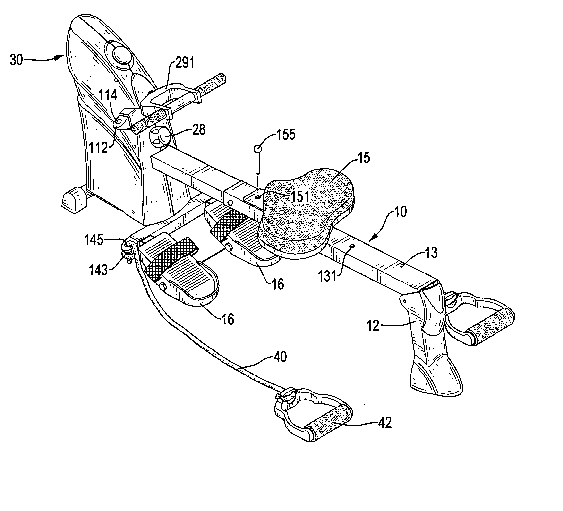
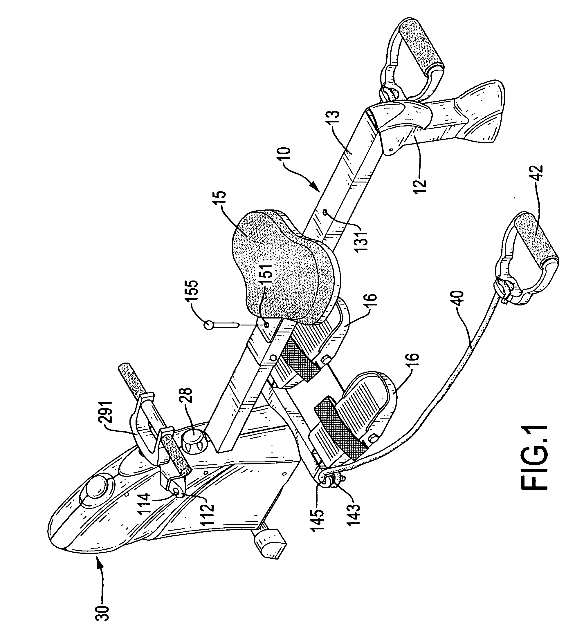
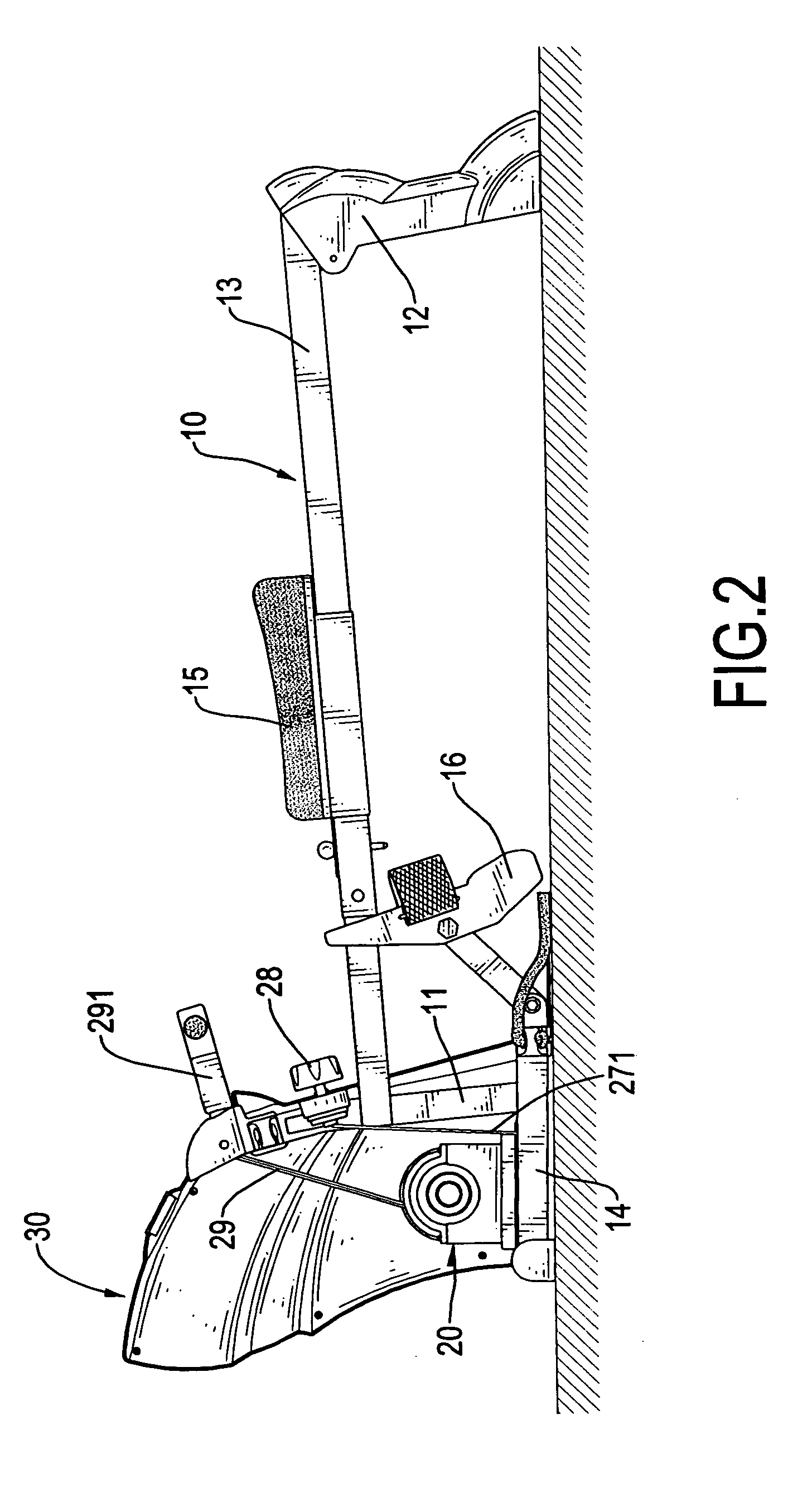
[0021] The resistance device is mounted between the base (21) and the flywheel (25) to provide a resistance to the flywheel (25). In a first embodiment, the resistance device comprises a resistance belt (26) and a resilient member (262). The resistance belt (26) is mounted around the flywheel (25) and has a first end securely attached to the base (21) and a second end. The resilient member (262) preferably is a spring and has a first end attached to the second end of the resistance belt (26) and a second end. With the resistance belt (26) mounted around the flywheel (25), the resistance belt (26) can provide a resistance to the rotation of the flywheel (25) with the friction between the resistance belt (26) and the flywheel (25).

[0022] The adjusting button (28) is rotatably attached to the housing (30) and connected to the resistance device with a cable (271). In the first embodiment, the cable (271) is connected to the second end of the resilient member (262). When the adjusting bu...

second embodiment

[0028] With reference to FIGS. 1 and 5, the resistant device comprises a metal collar (25A), a magnetic resistance element (26A) and a resilient member (262A). The metal collar (25A) is attached to an outer periphery of the flywheel (25). The magnetic resistance element (26A) is pivotally attached to the base (21) and corresponds to the metal collar (25A) on the flywheel (25). One end of the magnetic resistance element (26A) is connected to the cable (271). The resilient member (262A) is mounted between the base (21) and the magnetic resistance element (26A). The magnetic resistance element (26A) will provide an attractive force to the metal collar (25A) on the flywheel (25), such that a resistance force will be provided to the flywheel (25) during the rotation of the flywheel (25).

[0029] When the adjusting button (28) is rotated, the magnetic resistance element (26A) will be pulled far away from the metal collar (25A) or pushed near the metal collar (25A) by the resilient force pro...


PUM


Abstract

An exercising device has a frame, a seat, two pedals, a housing and an exercising mechanism. The exercising mechanism is mounted inside the housing and has a base, two brackets, a rotating axle, a torsion spring, a flywheel, a resistance device, a pulling rope and a first grip. The torsion spring is attached to the rotating axle. The flywheel is rotatably attached to the rotating axle in a unidirectional manner. The resistance device is mounted between the base and the flywheel to provide a resistance to the flywheel. The adjusting button is connected to the resistance device with a cable to adjust the resistance applied to the flywheel by means of rotating the adjusting button. The pulling rope reels around the rotating axle. The first grip is attached to the second end of the pulling rope.

Description

BACKGROUND OF THE INVENTION [0001] 1. Field of the Invention [0002] The present invention relates to an exercising device, and more particularly to a multi-functional exercising device that can provide multiple exercising functions and is versatile in use. [0003] 2. Description of Related Art [0004] Although indoor exercisers have become popular in recent years, the conventional indoor exerciser only has one function and is not versatile in use. A type of conventional exercising device with multiple functions is devised to solve the problem of an exercising device having only a single function, but the type of the conventional exercising device has a complex structure and a high cost. [0005] To overcome the shortcomings, the present invention tends to provide an exercising device to mitigate or obviate the aforementioned problems. SUMMARY OF THE INVENTION [0006] The main objective of the invention is to provide an exercising device having multiple functions and being versatile in us...

Claims


Application Information

Patent Timeline
IPC IPC(8): A63B69/06A63B21/02
CPCA63B21/018A63B21/153A63B21/157A63B21/225A63B22/0076A63B2022/0079
Inventor CHEN, PING
Owner CHEN PING
Why Eureka
Try Eureka