Inkjet printing apparatus

a technology of printing apparatus and inkjet, which is applied in the direction of printing, ironing boards, coatings, etc., can solve problems such as defective products

Active Publication Date: 2006-07-13
BROTHER KOGYO KK
View PDF8 Cites 20 Cited by
  • Summary
  • Abstract
  • Description
  • Claims
  • Application Information

AI Technical Summary

Benefits of technology

[0004] The present invention is advantageous in that an inkjet type printing apparatus is provided, which is capable of printing an image on a fabric accurately at a desired position thereof.
[0005] According to an aspect of the invention, there is provided an inkjet type fabric printing apparatus, which is provided with an inkjet head that ejects ink onto a fabric, the inkjet head reciprocally moving in main scanning direction and auxiliary scanning direction relative to the fabric, a platen that holds the fabric to extend on a plane substantially parallel with the main scanning direction and the auxiliary scanning direction with a first predetermined distance spaced from the inkjet head, and a positioning member on which the fabric is set the fabric is positioned on the platen in place in a direction parallel with the main scanning direction and the auxiliary scanning direction, at least one of a neck portion and a shoulder portion being thicker than a portion of the closing spread on the platen, the positioning member supporting the at least one of the neck portion and the shoulder portion of the fabric such that the at least one of the neck portion and a shoulder portion is spaced from the inkjet head by a second predetermined distance at which the at least one of the neck portion and the shoulder portion does not hinder the movement of the inkjet head.
[0022] According to a further aspect of the invention, there is provided an inkjet type fabric printing apparatus for printing an image on a predetermined area of a fabric. The printing device is provided with an inkjet head that ejects ink, the inkjet head reciprocally moving in main scanning direction and auxiliary scanning direction relative to the fabric, a platen that holds the fabric to extend on a plane substantially parallel with the main scanning direction and the auxiliary scanning direction with a first predetermined distance spaced from the inkjet head, and a positioning portion integrally formed on the platen, the positioning portion supporting the a reference portion of the fabric such that the fabric is held on the platen in place in a direction parallel with the main scanning direction and the auxiliary scanning direction. The reference portion is formed to be thicker than the other portion including the predetermined area, and the positioning portion supports the fabric such that the reference portion is spaced from the inkjet head by a second predetermined distance at which the reference portion does not hinder the movement of the inkjet head.

Problems solved by technology

Thus, the T-shirt cannot be accurately positioned, and thus the image is often printed out of position, resulting in defective products.

Method used


Image

  • Inkjet printing apparatus
  • Inkjet printing apparatus
  • Inkjet printing apparatus

Examples


first embodiment

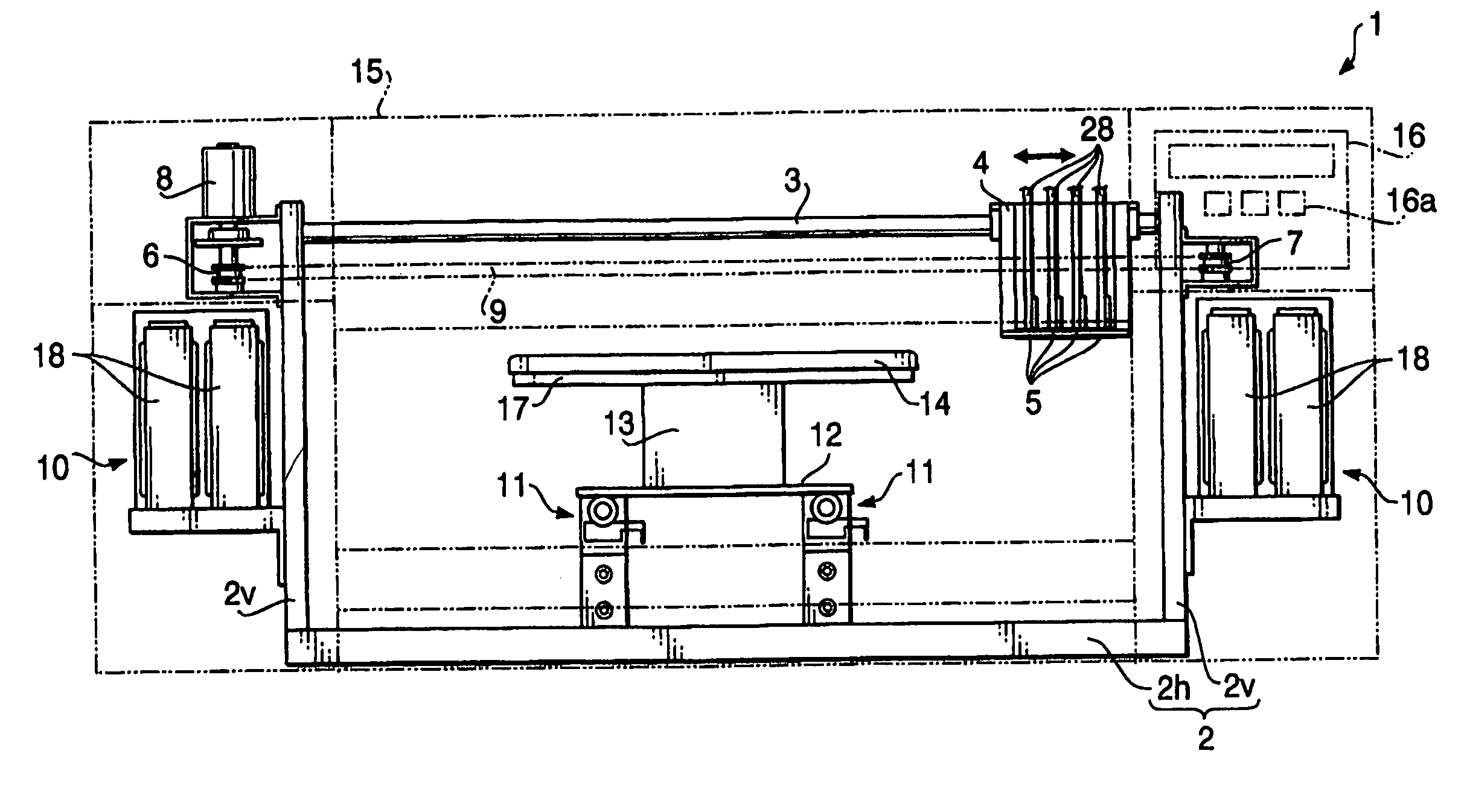
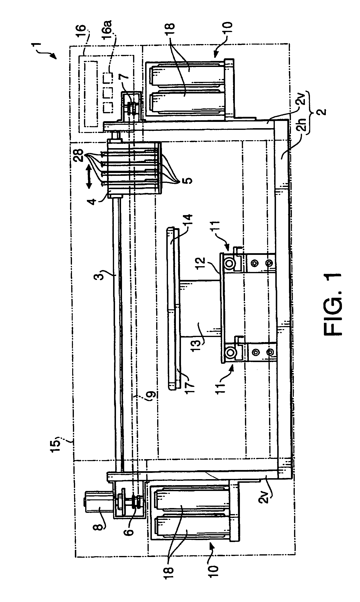
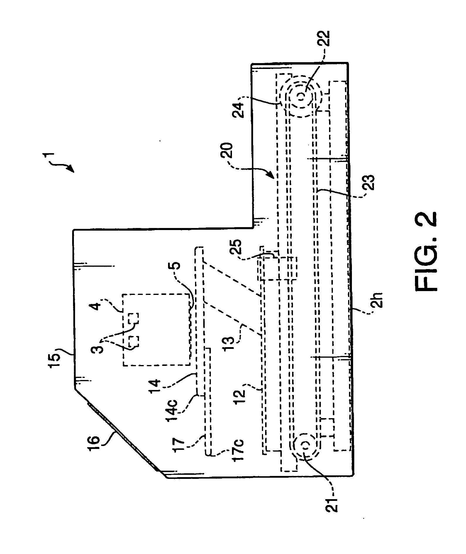
[0056]FIGS. 1 and 2 are a front view and a side view, respectively, of a fabric printing apparatus 1 according to a first embodiment of the invention. As shown in FIG. 1, the fabric printing apparatus 1 includes a frame 2 provided on a casing (which is schematically illustrated by chain double-dashed lines). The frame 2 includes a horizontal portion 2h horizontally disposed on the bottom of the fabric printing apparatus 1 and vertical portions 2v extending perpendicularly to and upward from both sides of the horizontal portion 2h.

[0057] A slide rail 3 is horizontally supported by the vertical portions 2v to extend between the upper ends thereof. A carriage 4 is mounted on the slide rail 3 slidably in a longitudinal direction of the slide rail 3, or a main scanning direction of the fabric printing apparatus 1. Four piezoelectric inkjet heads 5 are mounted on an undersurface of the carriage 4. Each inkjet head 5 corresponds to an ink of different color. Thus, these inkjet heads 5 can...

second embodiment

[0089] Hereinafter, a fabric printing apparatus according to a second embodiment of the invention will be described. Note that, hereinafter, elements substantially the same as those referred to in the first embodiment will be denoted by the same reference numbers and detailed description thereof will be omitted.

[0090]FIGS. 10 and 11 are a front view and a side view, respectively, of a fabric printing apparatus 100 according to a second embodiment of the invention.

[0091] The fabric printing apparatus 100 includes a structure similar to the fabric printing apparatus 1. That is, the fabric printing apparatus 100 has the frame 2, which includes the horizontal portion 2h and the vertical portions 2v, and the slide rail 3 supported between the vertical portions 2v. The fabric printing apparatus 100 is further provided with the carriage 4 slidably supported on the slide rail 3, and four piezoelectric inkjet heads 5 mounted on the carriage 4. The carriage is coupled with the endless belt ...


PUM


Abstract

An inkjet type fabric printing apparatus is provided with an inkjet head, a platen and a positioning member. The inkjet head reciprocally moves in main scanning direction and auxiliary scanning direction relative to a fabric (e.g., clothes). The platen holds the fabric to extend on a plane parallel with the main scanning direction and the auxiliary scanning direction with a first predetermined distance spaced from the inkjet head. On the positioning member, the fabric is set. The fabric is positioned on the platen in place in a direction parallel with the main scanning direction and the auxiliary scanning direction. The positioning member supports at least one of a neck portion and a shoulder portion of the fabric such that the neck portion and / or a shoulder portion is spaced from the inkjet head by a second predetermined distance.

Description

BACKGROUND OF THE INVENTION [0001] The present invention relates to an inkjet printing apparatus for printing on a fabric. [0002] U.S. Pat. No. 6,095,628, the disclosure of which is incorporated herein by reference, discloses an example of such an inkjet printing apparatus. The printing apparatus disclosed in the patent is provided with a platen that is translatable back and forth with respect to a housing and inkjet head thereof. In use, a T-shirt is loaded on the platen, and the platen is indexed rearwardly so as to place the T-shirt beneath the inkjet head of the apparatus. Then the inkjet head reciprocates above the T-shirt while the platen intermittently moves forward to print a desired image onto the T-shirt. [0003] In the conventional inkjet printing apparatus as mentioned above, the position of the T-shirt on the platen should be determined only by visual observation. Thus, the T-shirt cannot be accurately positioned, and thus the image is often printed out of position, resu...

Claims


Application Information

Patent Timeline
Patent Type & Authority Applications(United States)
IPC IPC(8): B41J2/01B41J3/407B41J11/06
CPCB41J2/01B41J3/28B41J3/4078B41J11/06
Inventor NIIMI, AKIKOWATARAI, KATSUYAFUKAYA, KOUSUKE
Owner BROTHER KOGYO KK
Why Eureka
Try Eureka