Loose tube optical cable having straight aggregation structure

a technology of optical cables and aggregations, applied in the direction of cables, instruments, fibre mechanical structures, etc., can solve the problems of increasing the cost of manufacturing, carrying and installing optical cables

Inactive Publication Date: 2006-07-13
LG CABLE LTD (KR)
View PDF4 Cites 7 Cited by
  • Summary
  • Abstract
  • Description
  • Claims
  • Application Information

AI Technical Summary

Benefits of technology

[0007] The present invention is designed to solve the problems of the prior art, and therefore an object of the present invention is to provide a loose tube optical cable having an unstranded structure which may not require insertion of unnecessary inclusions, make the tensile stress be focused on the tensile strength member though the loose tube optical fiber units are not helically or SZ twisted around the tensile strength member, and minimize the stress caused to the optical fiber due to the bending of the cable.
[0015] Generally, the prolonged reliability of the optical fiber is not affected when the maximum bending radius of the optical cable is more than 20 times of the optical cable diameter and the maximum modulus of elongation of the optical fiber is not more than 0.3% during installing the optical cable.
[0016] Thus, in the present invention having the loose tube optical fiber unit, the prolonged reliability of the optical fiber may be ensured when the maximum modulus of elongation of the optical fiber is not more than 0.3% at the maximum bending radius of the optical cable (equal to 20 times of the optical cable diameter) even though not helically nor SZ twisting the loose tube optical fiber unit around the tensile strength member.
[0020] In addition, the loose tube optical cable of the present invention may also include a binder for binding the aggregation in a longitudinal direction, and filler for preventing penetration of water, which is interposed between the cable coating and the aggregation.

Problems solved by technology

In addition, since the diameter and weight of the optical cable are not reduced due to the inclusions, there are increased the costs for manufacturing, carrying and installing the optical cable.

Method used


Image

  • Loose tube optical cable having straight aggregation structure
  • Loose tube optical cable having straight aggregation structure
  • Loose tube optical cable having straight aggregation structure

Examples


Embodiment Construction

[0031] Hereinafter, the present invention will be described in more detail referring to the drawings. First of all, terms and words used in the specification and the claims should be interpreted not in a limited normal or dictionary meaning, but to include meanings and concepts conforming with technical aspects of the present invention, based on the face that inventors may appropriately define a concept of a term to describe his / her own invention in a best way. Therefore, the configurations described in the specification and drawn in the figures are just most preferred embodiments of the present invention, not to show all of the technical aspects of the present invention. So, it should be understood that there might be various equalities and modifications to be replaced with them.

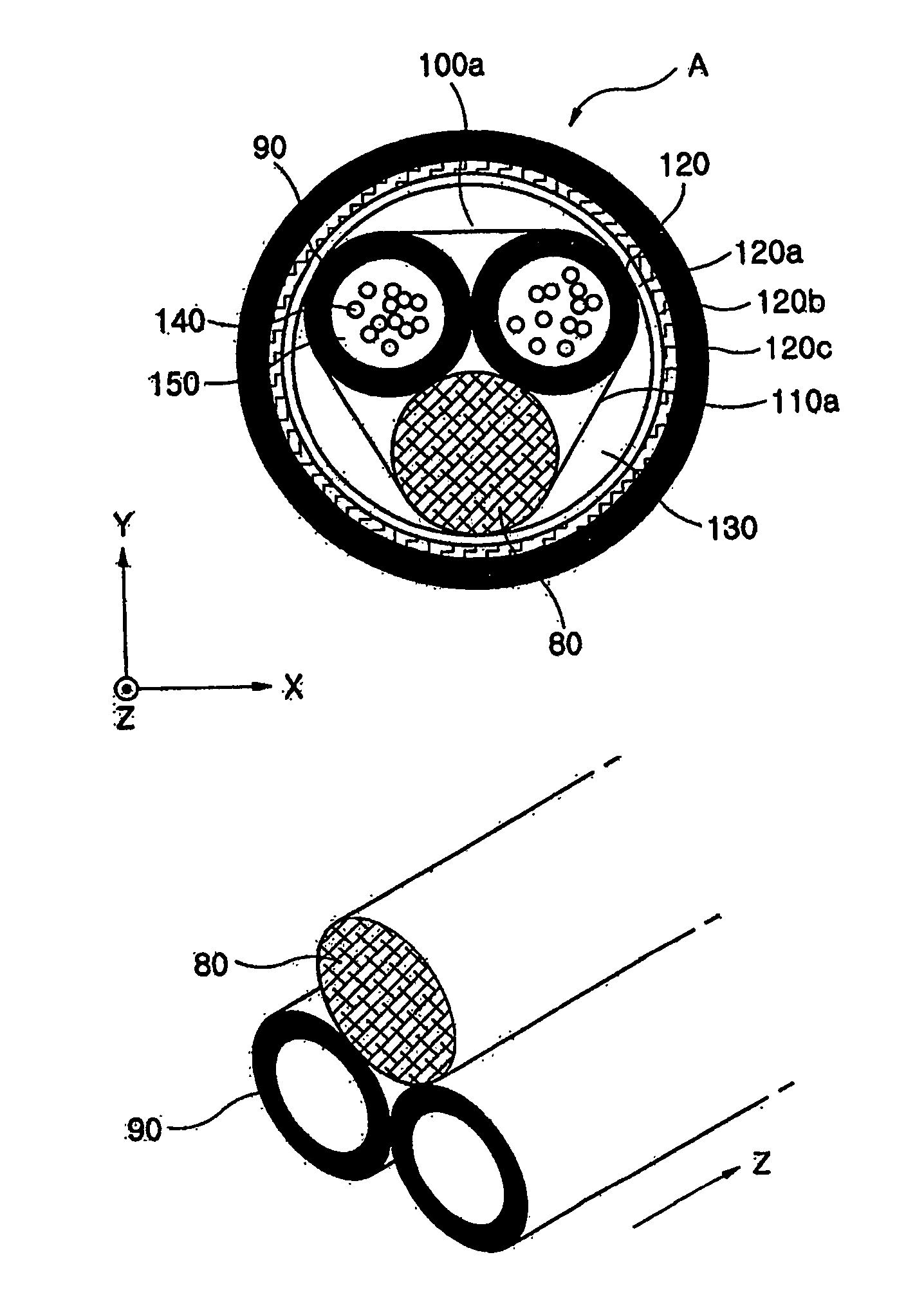
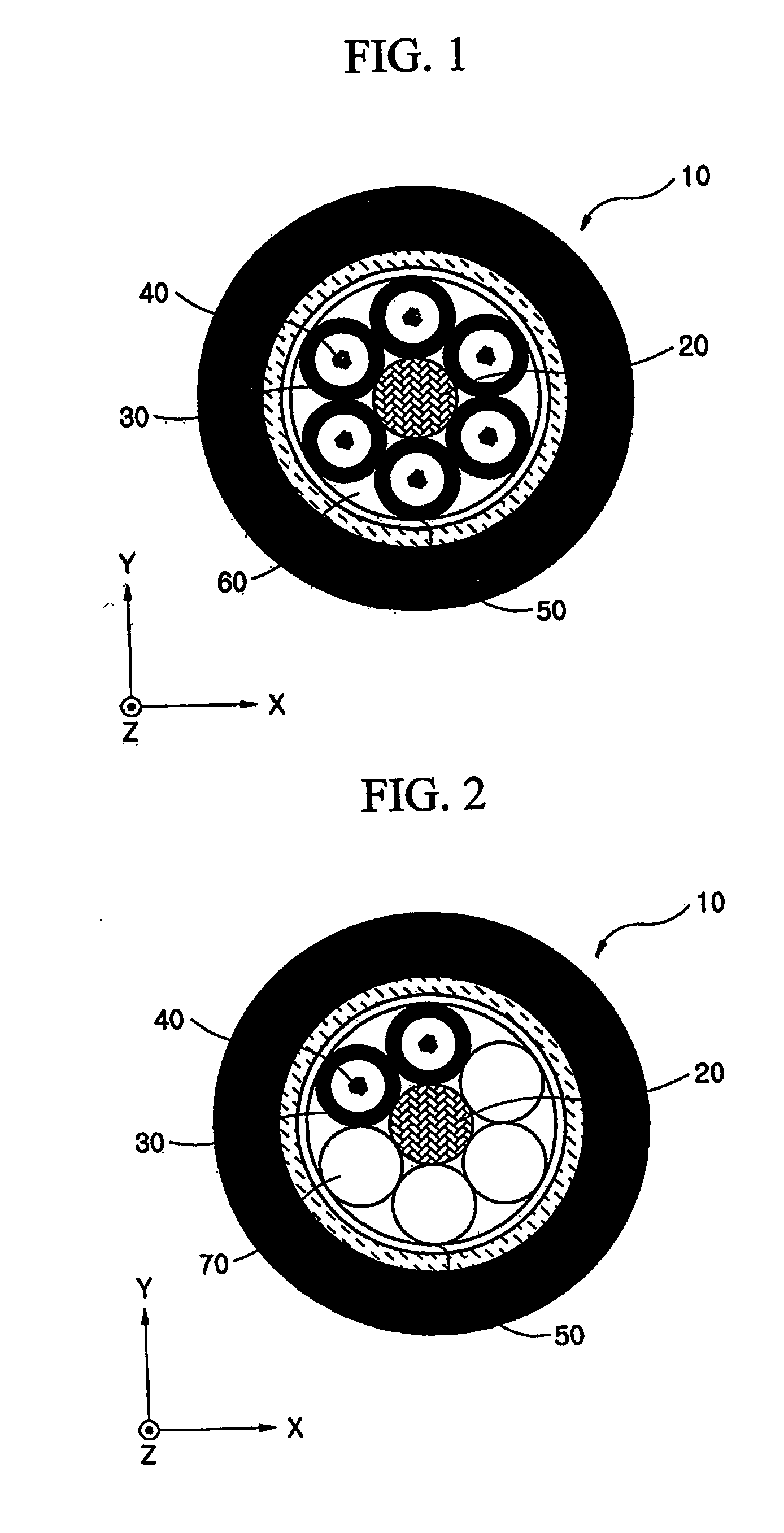
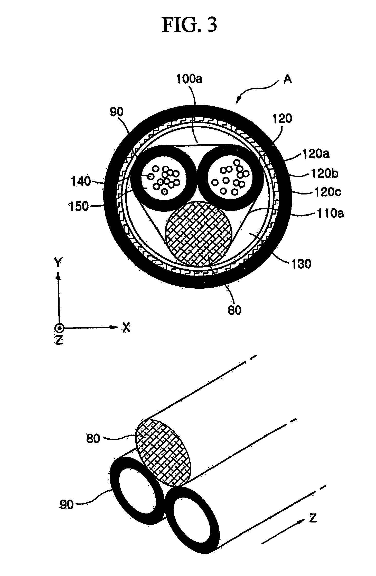
[0032]FIGS. 3 and 4 are sectional views showing loose tube optical cables respectively having 1+2 structure and 1+1 structure according to embodiments of the present invention. Here, “1+2 structure” means ...


PUM

PropertyMeasurementUnit
modulus of elongationaaaaaaaaaa
aggregationaaaaaaaaaa
tensile strengthaaaaaaaaaa

Abstract

Disclosed is a loose tube optical cable having an unstranded structure, which includes a tensile strength member longitudinally elongated and having a central axis deviated from the center of the optical cable, a loose tube optical fiber unit longitudinally elongated without intended twist against the tensile strength wire, and a cable coating for wrapping an aggregation in which the tensile strength member and the loose tube optical fiber unit are straightly aggregated. By suitably selecting geometric parameters of the tensile strength member and the loose tube optical fiber unit, the center of mass of the aggregation is positioned within the tensile strength member and the maximum modulus of elongation of the optical fiber is restricted within a predetermined range in a predetermined bending radius.

Description

TECHNICAL FIELD [0001] The present invention relates to a loose tube optical cable, and more particularly to a loose tube optical cable having an unstranded structure that has no inclusion for keeping an original form of the optical cable and has no intended twist of the loose tube on an outer circumference of a tensile strength member of the cable. BACKGROUND ART [0002] The optical fiber is generally classified into a loose tube optical cable and a ribbon slot optical cable depending on the structure of the optical cable core. Among them, the loose tube optical cable is configured so that a plurality of optical fiber units in which the required number of optical fibers are mounted in a plastic tube together with jelly compound (hereinafter, referred to as ‘loose tube optical fiber unit’) are stranded around a tensile strength member positioned at the center of the cable. At this time, a plurality of the loose tube optical fiber units are stranded around the tensile strength member ...

Claims


Application Information

Patent Timeline
Patent Type & Authority Applications(United States)
IPC IPC(8): G02B6/44H01B11/22
CPCG02B6/441G02B6/4429H01B11/22
Inventor KIM, TAE-GYOUNGSON, MIN
Owner LG CABLE LTD (KR)
Why Eureka
Try Eureka